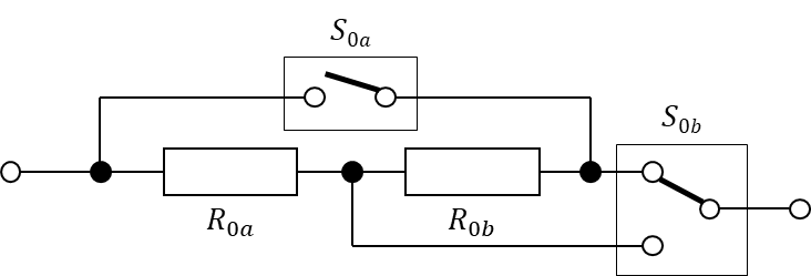
In the last post we had a look at a simple topology that allows us to switch between a series and a parallel connection of two resistors:
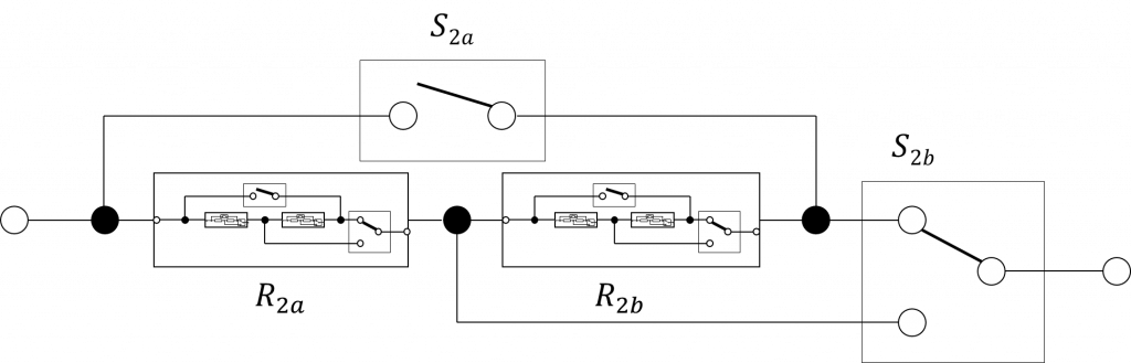
Now we’ll nest these structures so that we have four resistors:

The interesting part here is that two of the four switch states of the outer structure don’t provide any new resistance values: With \(S_{1a}\) open and \(S_{1b}\) bypassing the \(R_{1b}\) we’re left with \(R_{1a}\). Again, this assumes the \(R_{1a} = R_{1b}\). If \(S_{1a}\) is closed and \(S_{1b}\) in the upper position, then the total resistance will be 0, exactly like with only \(R_{1a}\). Here I assume ideal switches. The series and parallel connection of both \(R_{1a}\) and \(R_{1b}\) alone is worth it though.
Doing that once more and we get eight resistors, barely visible in this picture, but with a similar effect like with the previous nesting.
Because there are 14 switches there are \(2^{14}=16,384\) different switch states. As briefly discussed, many switch states might lead to the same resistance values (actually, by far not only the two examples described above). In fact, as we will see later, much more than half of the switch states result in a short circuit.
However, states with equal resistances might not be equally suited for the intended application, because in some cases they differ in the power rating we can achieve. But even then, for certain resistance values there might be multiple states with the same resistance and power rating, but with a different number of active switches. This could minimize the contact resistance (but this is not necessarily the case with the dual throw switch) and it’s generally a good idea to energize as few relays as possible.
This begs the following three questions:
- How many and which distinct resistance values can be selected?
- Which power rating can we achieve per resistance value?
- What is the best switch combination (least number of relays energized for the highest power rating) to realize each of the selectable resistance values?
To answer this I wrote a small python script that calculates these things for us. I’ll assume all resistors are \(10 \text{ }\Omega\) with a \(50\text{ W}\) power rating. The results are presented in the following table. Let’s have a look at the columns first, as some might require some additional explaining:
- Number of valid Switch combinations: How many different switch combinations achieve the same resistance value (not necessarily the same power dissipation capability)
- Maximum Power: Calculated power rating
- Binary Encoded Switch combination: A binary-encoded switch combination that uses the lowest number of energized relays (for use in the software)
- Energized Switches: Minimum number of switches that have to be energized to achieve the specified resistance value
| # | Resistance (\(\Omega\)) | Number of Valid Switch Combin. | Maximum Power (\(\text{W}\)) | Binary Encoded Switch Combin. | Energized Switches |
|---|---|---|---|---|---|
| 1 | 0 | 9472 | nan | 325 | 4 |
| 2 | 1.25 | 1 | 400 | 16383 | 14 |
| 3 | 1.428571 | 4 | 350 | 16127 | 13 |
| 4 | 1.538462 | 4 | 325 | 15615 | 12 |
| 5 | 1.666667 | 18 | 300 | 12799 | 11 |
| 6 | 1.818182 | 12 | 275 | 15551 | 11 |
| 7 | 2 | 48 | 250 | 12735 | 10 |
| 8 | 2.142857 | 4 | 233.333333 | 13055 | 11 |
| 9 | 2.222222 | 50 | 225 | 12415 | 9 |
| 10 | 2.272727 | 4 | 220 | 12543 | 10 |
| 11 | 2.307692 | 4 | 216.666667 | 12479 | 9 |
| 12 | 2.352941 | 2 | 212.5 | 12351 | 8 |
| 13 | 2.5 | 209 | 200 | 1087 | 7 |
| 14 | 2.727273 | 8 | 183.333333 | 13051 | 10 |
| 15 | 2.857143 | 60 | 175 | 12723 | 8 |
| 16 | 2.941176 | 8 | 170 | 12539 | 9 |
| 17 | 3 | 8 | 166.666667 | 12475 | 8 |
| 18 | 3.076923 | 4 | 162.5 | 12347 | 7 |
| 19 | 3.157895 | 8 | 158.333333 | 13043 | 9 |
| 20 | 3.333333 | 384 | 150 | 1083 | 6 |
| 21 | 3.448276 | 8 | 145 | 12531 | 8 |
| 22 | 3.529412 | 8 | 141.666667 | 12467 | 7 |
| 23 | 3.636364 | 4 | 137.5 | 12339 | 6 |
| 24 | 3.75 | 28 | 133.333333 | 12747 | 8 |
| 25 | 4 | 370 | 125 | 1075 | 5 |
| 26 | 4.166667 | 28 | 120 | 12487 | 7 |
| 27 | 4.285714 | 28 | 116.666667 | 12423 | 6 |
| 28 | 4.444444 | 14 | 112.5 | 12295 | 5 |
| 29 | 4.615385 | 8 | 108.333333 | 13042 | 8 |
| 30 | 5 | 933 | 400 | 15408 | 6 |
| 31 | 5.263158 | 8 | 95 | 12530 | 7 |
| 32 | 5.454545 | 8 | 91.6666667 | 12466 | 6 |
| 33 | 5.714286 | 4 | 87.5 | 12338 | 5 |
| 34 | 5.833333 | 4 | 262.5 | 3839 | 11 |
| 35 | 6 | 32 | 187.5 | 13040 | 7 |
| 36 | 6.5 | 4 | 203.125 | 3327 | 10 |
| 37 | 6.666667 | 356 | 300 | 12400 | 5 |
| 38 | 7.142857 | 32 | 280 | 12528 | 6 |
| 39 | 7.333333 | 8 | 229.166667 | 3323 | 9 |
| 40 | 7.5 | 50 | 266.666667 | 12464 | 5 |
| 41 | 8 | 20 | 250 | 12336 | 4 |
| 42 | 8.333333 | 28 | 166.666667 | 507 | 8 |
| 43 | 8.571429 | 28 | 131.25 | 12363 | 6 |
| 44 | 9 | 28 | 180 | 499 | 7 |
| 45 | 9.166667 | 4 | 103.125 | 3263 | 9 |
| 46 | 9.375 | 8 | 120 | 12491 | 7 |
| 47 | 10 | 1074 | 200 | 1072 | 3 |
| 48 | 10.666667 | 8 | 120 | 3251 | 7 |
| 49 | 10.909091 | 4 | 103.125 | 12299 | 5 |
| 50 | 11.111111 | 28 | 180 | 12355 | 5 |
| 51 | 11.666667 | 28 | 131.25 | 498 | 6 |
| 52 | 12 | 28 | 166.666667 | 12354 | 4 |
| 53 | 12.5 | 20 | 250 | 12483 | 6 |
| 54 | 13.333333 | 50 | 266.666667 | 3131 | 7 |
| 55 | 13.636364 | 8 | 229.166667 | 12419 | 5 |
| 56 | 14 | 32 | 280 | 3123 | 6 |
| 57 | 15 | 356 | 300 | 12418 | 4 |
| 58 | 15.384615 | 4 | 203.125 | 12291 | 4 |
| 59 | 16.666667 | 32 | 187.5 | 3122 | 5 |
| 60 | 17.142857 | 4 | 262.5 | 12290 | 3 |
| 61 | 17.5 | 4 | 87.5 | 767 | 9 |
| 62 | 18.333333 | 8 | 91.6666667 | 763 | 8 |
| 63 | 19 | 8 | 95 | 755 | 7 |
| 64 | 20 | 933 | 400 | 12288 | 2 |
| 65 | 21.666667 | 8 | 108.333333 | 754 | 6 |
| 66 | 22.5 | 14 | 112.5 | 127 | 7 |
| 67 | 23.333333 | 28 | 116.666667 | 123 | 6 |
| 68 | 24 | 28 | 120 | 115 | 5 |
| 69 | 25 | 370 | 125 | 208 | 3 |
| 70 | 26.666667 | 28 | 133.333333 | 114 | 4 |
| 71 | 27.5 | 4 | 137.5 | 255 | 8 |
| 72 | 28.333333 | 8 | 141.666667 | 251 | 7 |
| 73 | 29 | 8 | 145 | 243 | 6 |
| 74 | 30 | 384 | 150 | 144 | 2 |
| 75 | 31.666667 | 8 | 158.333333 | 242 | 5 |
| 76 | 32.5 | 4 | 162.5 | 191 | 7 |
| 77 | 33.333333 | 8 | 166.666667 | 187 | 6 |
| 78 | 34 | 8 | 170 | 179 | 5 |
| 79 | 35 | 88 | 175 | 75 | 4 |
| 80 | 36.666667 | 8 | 183.333333 | 178 | 4 |
| 81 | 40 | 209 | 200 | 16 | 1 |
| 82 | 42.5 | 2 | 212.5 | 63 | 6 |
| 83 | 43.333333 | 4 | 216.666667 | 59 | 5 |
| 84 | 44 | 4 | 220 | 51 | 4 |
| 85 | 45 | 50 | 225 | 7 | 3 |
| 86 | 46.666667 | 4 | 233.333333 | 50 | 3 |
| 87 | 50 | 48 | 250 | 6 | 2 |
| 88 | 55 | 12 | 275 | 11 | 3 |
| 89 | 60 | 18 | 300 | 1 | 1 |
| 90 | 65 | 4 | 325 | 3 | 2 |
| 91 | 70 | 4 | 350 | 2 | 1 |
| 92 | 80 | 1 | 400 | 0 | 0 |
Since the selected topology does not feature the option to open the circuit, an additional series-connected relay is required. This relay is not included in the total number of energized relays.