I‘ve always been fascinated by lights and all kinds of displays. Nixie tubes certainly are no exception. So I had to built my own Nixie clock as probably every EE does.
A word of caution: Nixie tubes require high voltages that might cause damage, serious injury or death. If you’re not authorized or qualified to work on such devices, don’t do it. I don’t take any responsibility for actions you take or the results of these actions. You do everything at your own risk.
The small version.

I started with a fairly small design based on a custom PCB featuring six IN-8 tubes. The schematics are heavily inspired by 0x7d.com’s work which I really like (https://0x7d.com/2017/nixie-tube-clock/). The most obvious changes were the addition of two extra digits for displaying seconds and the small glow tubes separating the hours, minutes and seconds. And of course the form factor of the PCB. Also, each tube has its own RGB LED and some additional switch buttons should improve the UI a bit.
On a more technical level there are many differences too, some to make my life much easier: I didn’t implement USB C and used a very compact high quality high voltage supply module (NCH8200HV). Choosing a STM32 with more pins meant that I could use its built-in Real-Time-Clock peripheral (dedicated VBAT pin).
As with any good prototype, errata in the schematics/footprints made one or two high quality bodges necessary. A matter of more concern: While the step down converter was readily available at the planning stage, things changed quite quickly due to the ongoing chip shortage. And I couldn’t find any pin compatible device whatsoever. During layout I somehow managed to place all the components in such a way that I could solder in a LD1117 linear regulator (DPAK), almost like I had anticipated this happening – I did not.
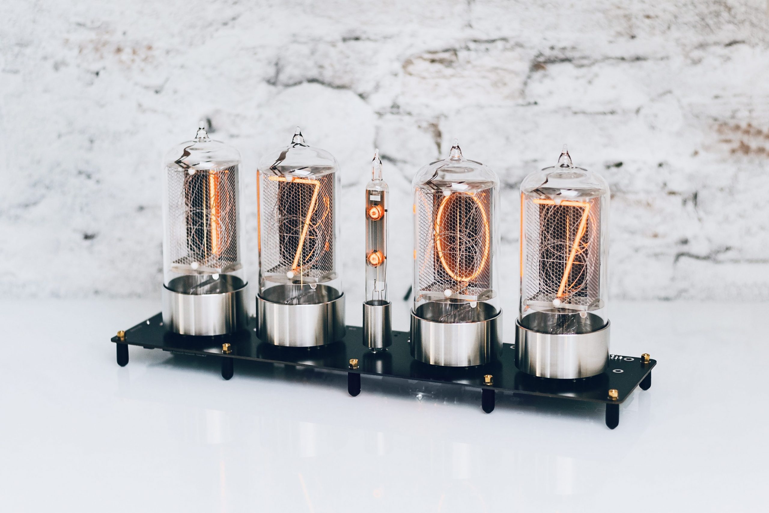
The big version.

It wasn’t long before I wanted to build a bigger version of the clock. So a few months back I ordered five Nixie tubes. Not just any tubes, but the beautiful R|Z568M built by Dalibor Farny. Although I really enjoy to such electronics projects, after seeing the calming glow of those tubes I wanted to be done with it as quickly as possible… One feature I wanted to include this time though: WiFi.

I’m not the biggest fan of the ESP series microcontrollers, so I decided to go all in and use a Raspberry PI Zero W. One of the issues with this approach is boot time. Also, I didn’t feel comfortable to handle time-critical tasks (e. g. dimming) on the RPi. So I ended up recycling much of the STM32 design (and code) from the previous version and just adding a RPi to it. The RPi provides access via a REST API written in Python and sends simple commands to the STM32 (I2C). Like with the small version, the STM32 does all the actual work. Way too complicated and overkill, but in my case fairly convenient.