While playing with an old Hameg HM504 and the Tektronix 465B oscilloscope that I repaired recently, I thought that I should do yet another mandatory tinker project: Using a microcontroller to write text on an oscilloscope screen via the XYZ-mode. And so I designed a small USB powered board around the STM32G441KBT6 which seems to be my go-to microcontroller nowadays. Its fairly capable dual channel 12-bit DAC (up to 5 MSPS) comes in really handy for generating the x- and y-components. Initially I thought about using a discrete 8-bit R2R network to modulate the brightness with the Z input, but after testing the circuit I finally decided keep it simple and just implement blanking with just a single GPIO output.
(There also is a slight signal integrity issue with the R2R network, where I noticed some z-component content on the DAC outputs. It might have been a poor PCB layout – the DAC lines are routed very close to eight synchronously and fast switching R2R network GPIOs, it also might have been power/decoupling related. After deciding against using the R2R network I didn’t bother to look into that, although this might have been the most interesting part of the project 🙂 Anyways…)
All three channels are buffered by an OPA4991 opamp. The reason for this choice: I accidentally ordered 5 of those devices in a somewhat strange SOT23 (14) package instead of the more conventional SOIC (14) that I would normally use, so I was looking for an application where I didn’t care about using this package. With Rail-to-Rail Inputs/Outputs the opamp seemed like a decent option. I chose a gain of 1 for both the x- and y-channels: Generally speaking, having an output voltage of about 3.3V peak-to-peak is fine for the x- and y-channels (many oscilloscopes provide a fine/vernier adjustment), though it might be too low to fully blank the screen. Therefore the opamp is supplied with 5V coming from the USB connector, enabling a z-output gain setting that brings the Z output close to 5V peak-to-peak.
The opamp might be a limiting factor for higher display resolutions and refresh rates because of its GBW of 4.5 MHz and slew rate of 21V/µs. For the z-axis specifically a logic gate might have been a better fit, but again, I wanted to use this particular opamp. (More importantly, at the time I didn’t know that I would scrap the idea to use the R2R-DAC for an actual brightness control.)
The software includes a display driver that provides functions for generating different graphics objects and characters. Those are written to an 128×128 pixel display RAM, organized in pages of 1 byte. Only the active pixels are then converted to the analog domain by the aforementioned DACs/GPIO in order to achieve a reasonably high frame rate of about 60fps while maintaining a decent “on” time of 2µs for each pixel. Obviously, these frame rates would drop if too many pixels were active at the same time. This is likely not an issue, even if the display is completely filled with text (assuming a typical 7×5 font).
As with almost all of my projects, the software supports SCPI commands, in this case to draw objects like pixels, lines, rectangles, ellipses and charcters/text.

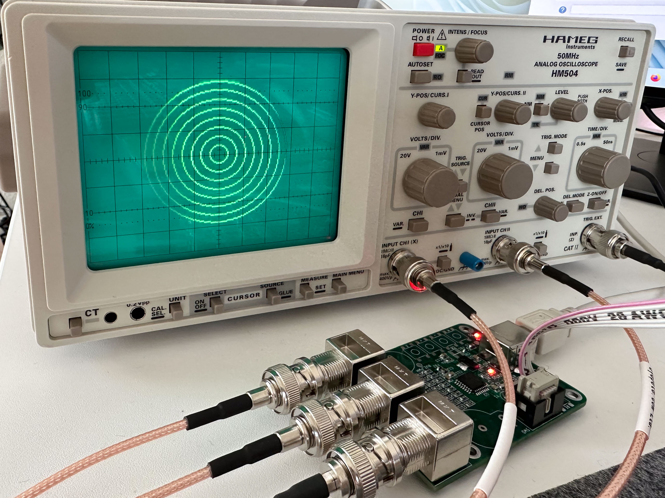
The XYZ mode is where good old analog oscilloscopes shine: I don’t think that my Siglent scope supports a Z input for brightness modulation at all, not to mention the generally worse looking image in this particular mode. If you try something like this with a digital scope, consider reducing the memory depth significantly, which might help a bit. So let’s have a look at the results:
(Please excuse the uneven brightness of the pixels in the pictures – these are smartphone pictures, so I didn’t have full control over the exposure time.):

With the provided 5V peak the Z input of the Tektronix doesn’t completely blank the screen. This is the reason for the still fairly bright dot on the right-hand side. In contrast, the HAMEG 504 fully blanks the screen with Z inputs as low as 4.5V. The 465B’s behavior is in accordance with the note provided next to the Z input:

Will I actually use this board? Probably not, not on a regular basis anyway. But it certainly was fun to build 🙂