20240412_175332608_iOS

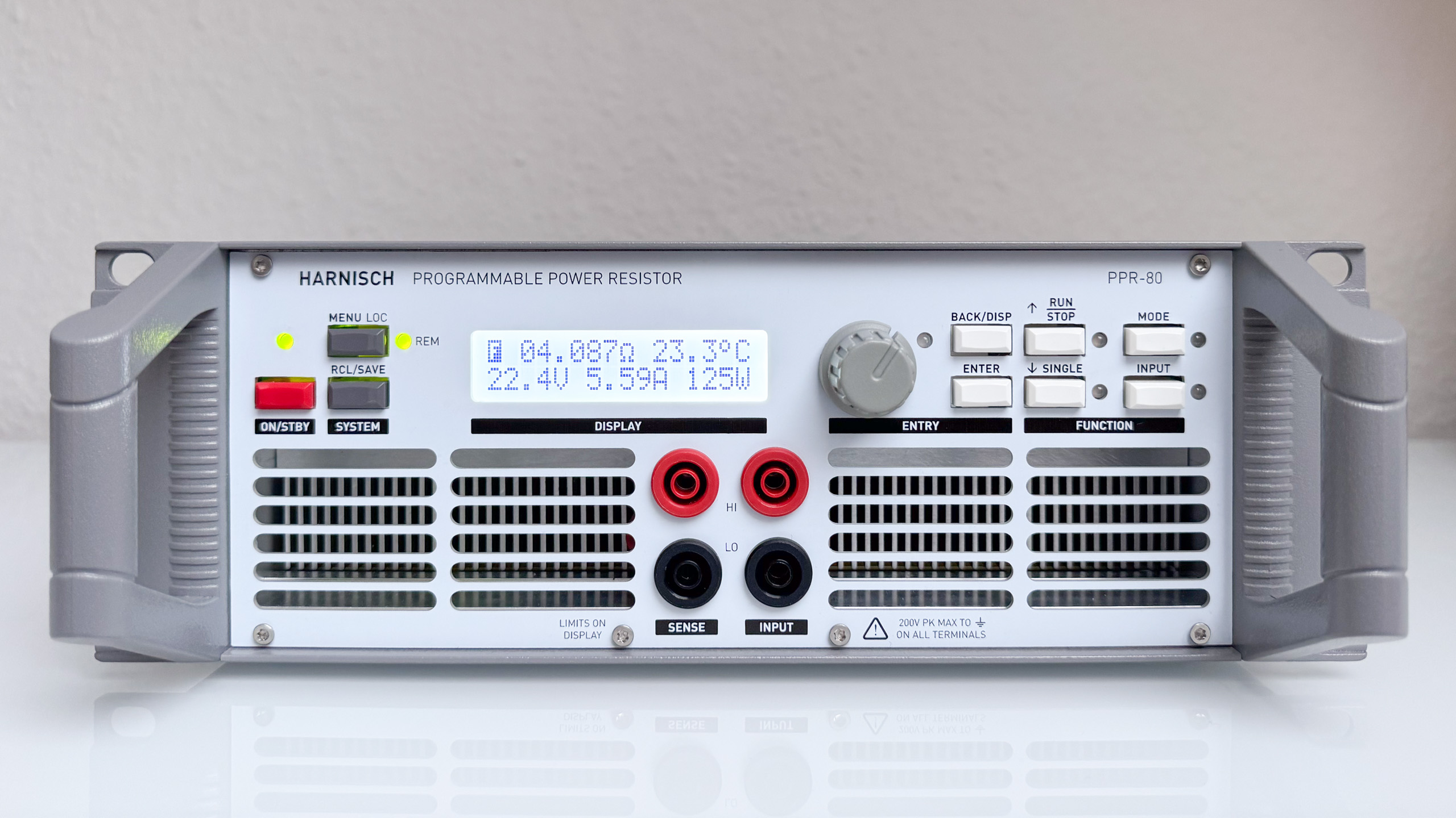
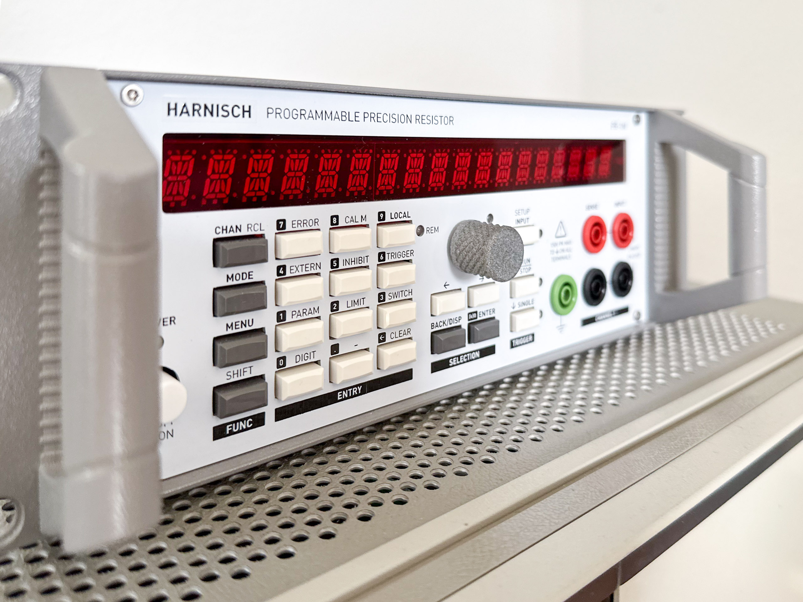
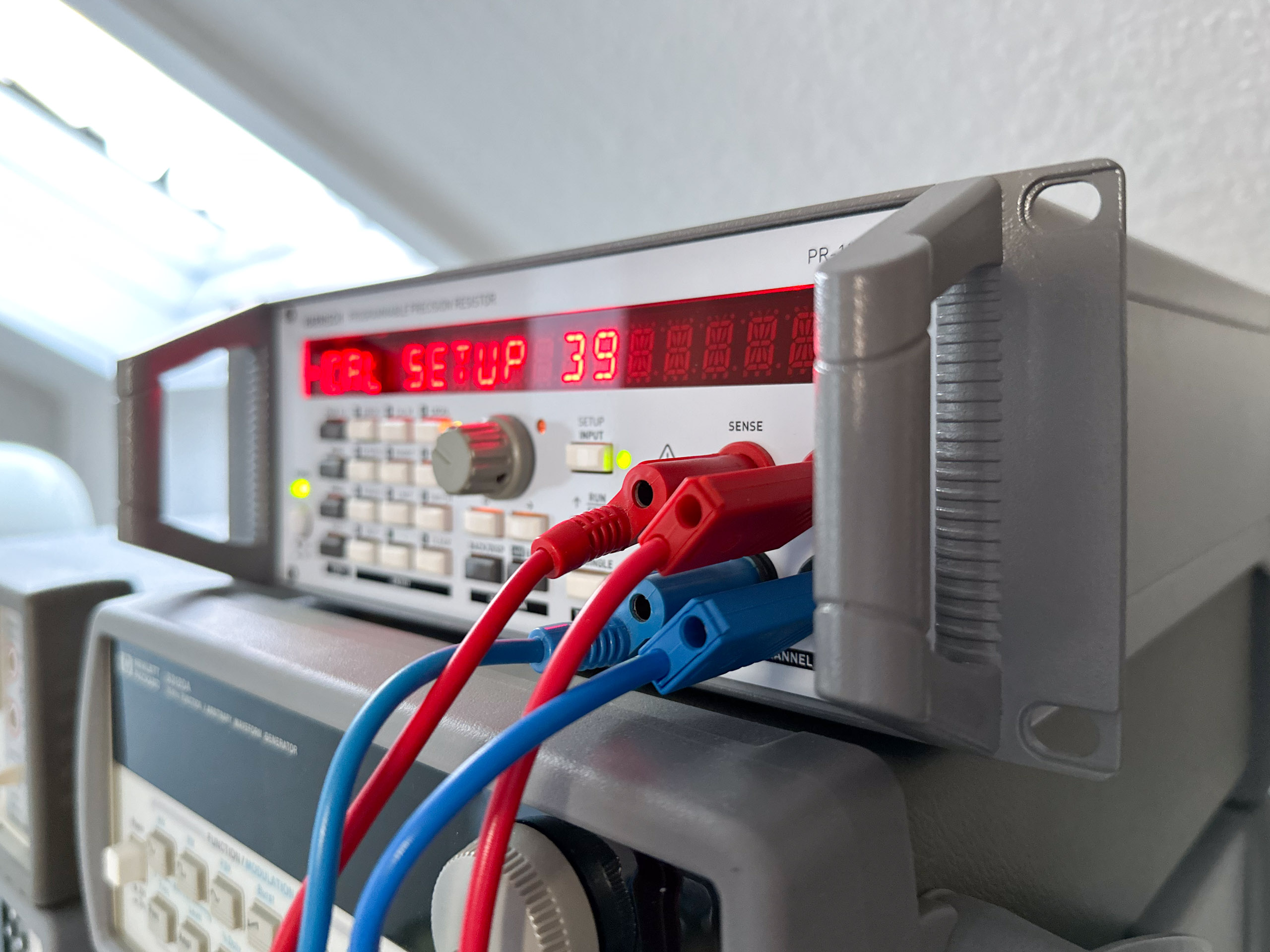
Programmable Power Resistor: Final Product

Although the Programmable Power Resistor re-uses some components, many design ideas and a good portion of the software of the Programmable Decade Resistor (Programmable Precision Resistor), there were many changes and also some improvements regarding some aspects of the mechanical construction and the code. Rear panel with two 60mm fans, USB connector and Line input Features and specs So now it’s time to present the feature list/specs: ...

April 12, 2024 · 4 min · Sebastian
system

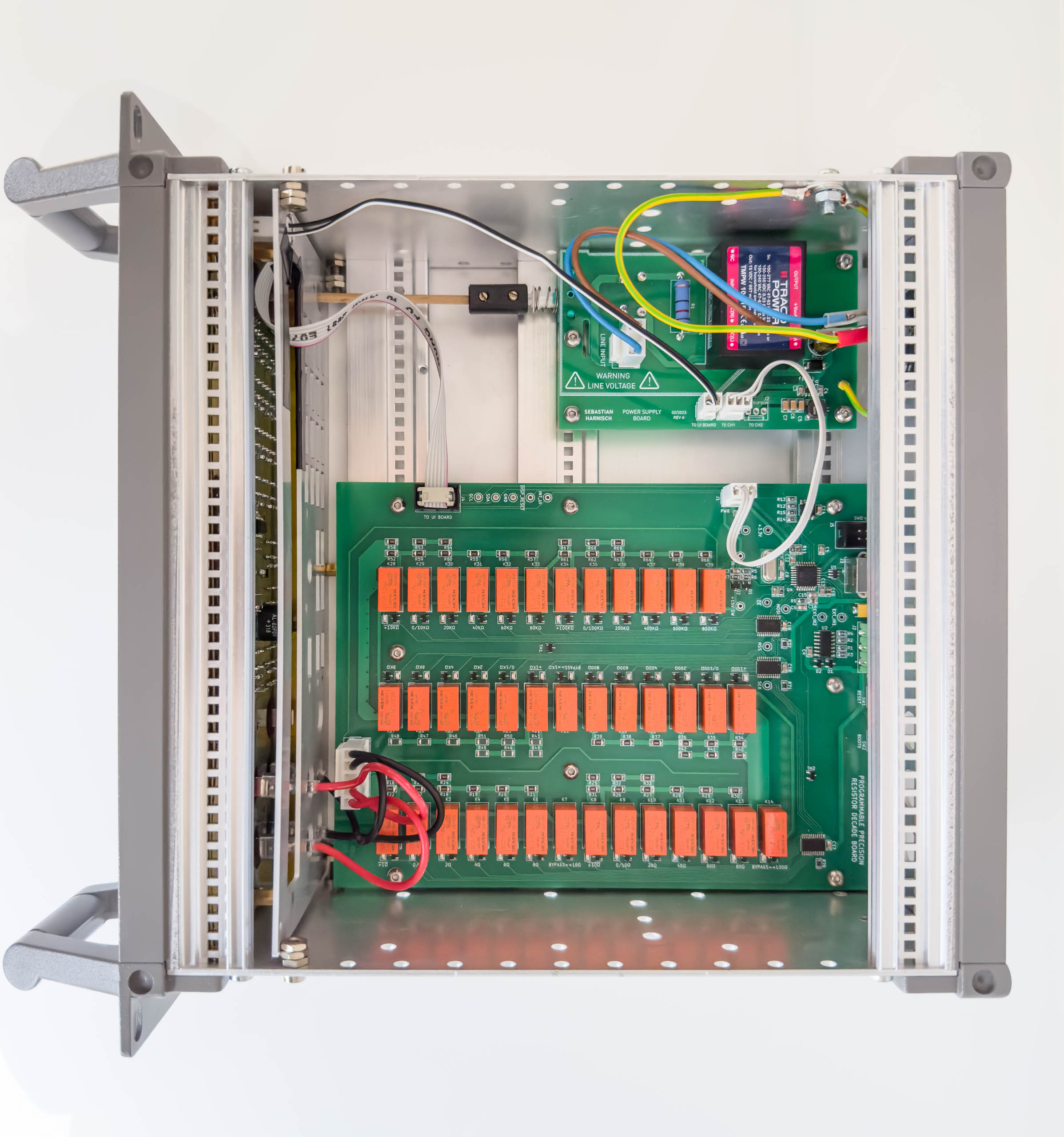
Programmable Power Resistor: System Design

The Programmable Power Resistor consists of two large boards: The User Interface and Controller Board and the Relay and Interface Board. Because of the use of relays that isolate the input from the circuits, all circuits can be and therefore are earth-referenced. The only microcontroller, a STM32G441RBT6, is located on the User Interface and Controller Board. It implements a SCPI interface via USB (VCOM), the user interface and the logic to control the relays. All relays, the relay driver circuits, some external and internal interfaces and the AC/DC converter can be found on the **Relay and interface Board **. ...

March 29, 2024 · 1 min · Sebastian
20240314_231949582_iOS

Programmable Power Resistor: Topology (2)

In the last post we had a look at a simple topology that allows us to switch between a series and a parallel connection of two resistors: Now we’ll nest these structures so that we have four resistors: The interesting part here is that two of the four switch states of the outer structure don’t provide any new resistance values: With S1aS_{1a} open and S1bS_{1b} bypassing the R1bR_{1b} we’re left with R1aR_{1a}. Again, this assumes the R1a=R1bR_{1a} = R_{1b}. If S1aS_{1a} is closed and S1bS_{1b} in the upper position, then the total resistance will be 0, exactly like with only R1aR_{1a}. Here I assume ideal switches. The series and parallel connection of both R1aR_{1a} and R1bR_{1b} alone is worth it though. ...

March 15, 2024 · 5 min · Sebastian
20240308_225127158_iOS

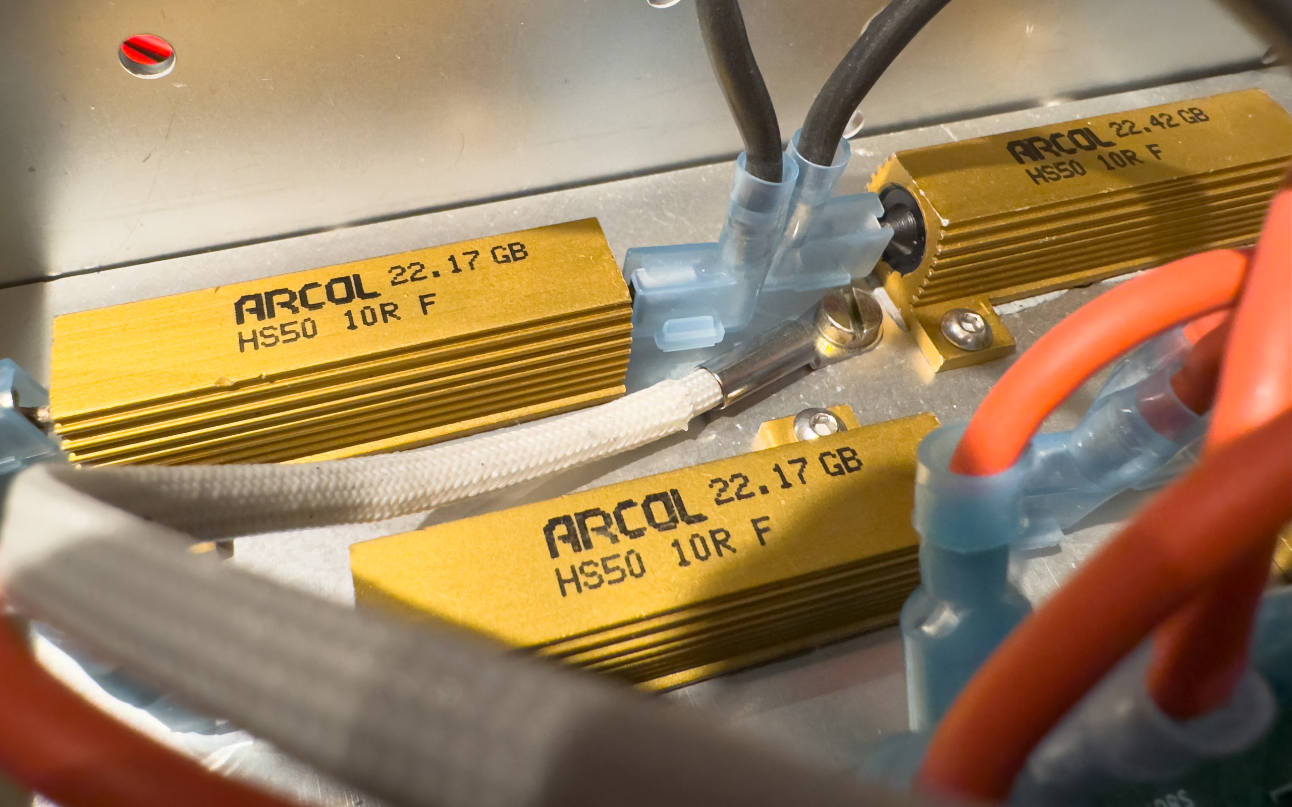
Programmable Power Resistor: Topology (1)

For the performance checks and calibration of my Agilent 6811B AC Power Source/Analyzer (375VA) I need a 20 Ohm resistor with a ton of power handling capability. The original plan was to mount 8 wire wound 50W resistors on a heat sink and be done with it. Then I thought: Why not reuse all the code I’ve already written for the programmable resistor and build a programmable high power resistor that can complement my DC load for AC applications. ...

March 9, 2024 · 2 min · Sebastian
20230501_173814208_iOS

Programmable Decade Resistor: Cost

I didn’t really think about the BOM cost of my programmable decade resistor until I was asked. Then I also wanted to know. It is fairly difficult to put a number to what I paid, since I had a lot of components left from other projects that I could use. This includes not only cheap chip resistors and MLCCs, but also connectors etc. Normally I order from both mouser and digikey, but for some of the industry-standard components, connectors etc I use local distributors. This is why I’ll only give a very rough estimate for the per unit costs including taxes (not including any shipping costs). For some of the parts like the PCBs there is a minimum order quantity that will increase the cost in most DIY scenarios. ...

September 13, 2023 · 2 min · Sebastian
20230407_133244694_iOS-Bearbeitet

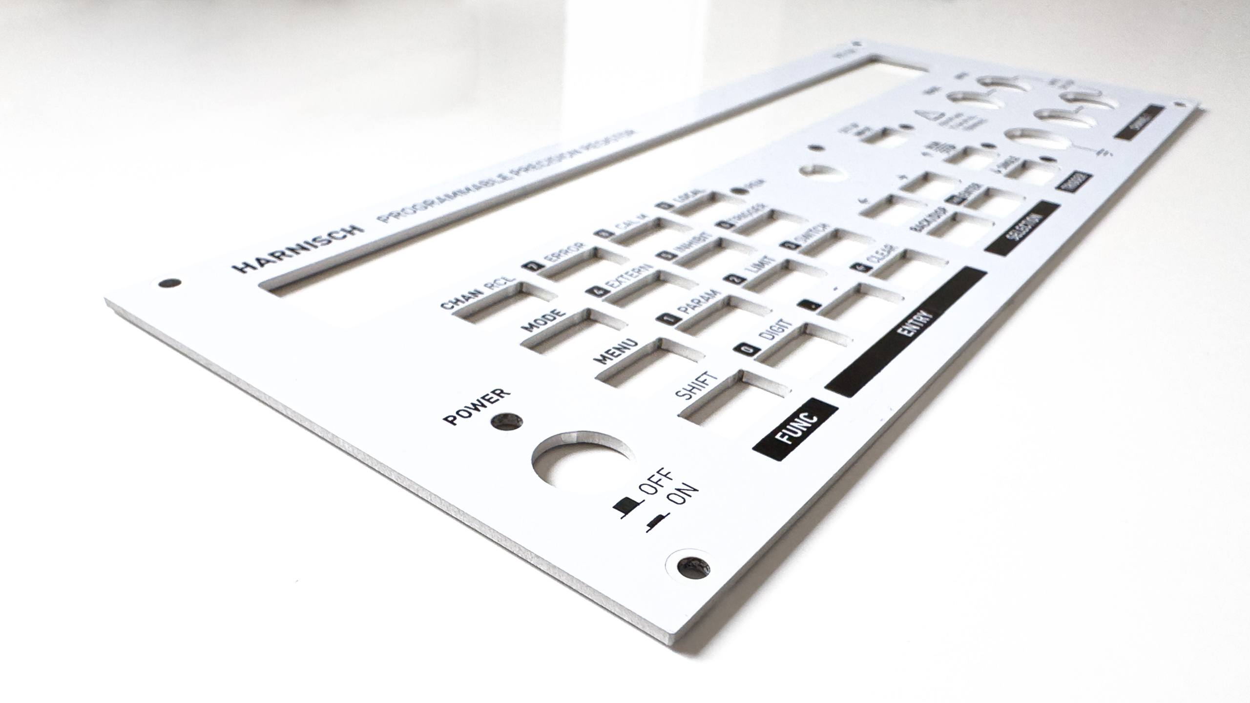
Programmable Decade Resistor: Panels

I was asked a few times how I did the front and rear panels, so this is what I’d like to talk about in this blog. There are different ways to achieve a similar result. For me, the easiest and most cost-effective solution was to just design another PCB - I know how KiCAD works and it does everything I need it to do. The basics Depending on the actual use case you can use a regular FR-4 board. For this project, however, I chose an aluminum PCB. Those only have one copper layer and the prototyping service might specify different process parameters for slot width etc. But other than that it is very similar to designing a regular PCB. ...

August 31, 2023 · 4 min · Sebastian
20230825_135701858_iOS

Programmable Decade Resistor: Components

After being asked about some aspects of the mechanical design and components used a few times, I’d like to address those questions. I have to admit that I’m neither very good at mechanical design, nor do I have a 3d printeror a workshop where I can do metal work myself. That being said, I was still able to design a reasonably professional looking device and bring it to life with the help of modern prototyping services. ...

August 25, 2023 · 2 min · Sebastian
20230714_190831358_iOS

Programmable Decade Resistor: Improved results

After the modification described in the previous post I let the the “adjustment”/calibration procedure run again. Five days later I repeated the calibration (not the adjustment). As before, all measurements are performed with an Agilent 34401A 6.5 digit multimeter. Accuracy of the resistance First up is a diagram that shows the absolute value of the deviation of the measurement value from the setpoint. The tested values are grouped as follows: ...

August 5, 2023 · 7 min · Sebastian
20230721_122849287_iOS

About word clocks...

A bit over a decade ago I built a word clock - one of my first microcontroller projects. The project was fairly expensive: It uses a large stainless steel front panel (ca. 39cm x 39cm, laser cut) and a similar sized PCB. Over the years I had to resolder one or two of the RGB LEDs and replace a failed one, but other than that it’s still working as intended. ...

July 27, 2023 · 3 min · Sebastian
20230716_122355688_iOS

Programmable Decade Resistor: Optimization

I went into this project with the thought that it will be a rather small one. This certainly influenced some decisions I made along the way. Now that the project had evolved into a much larger thing than initially anticipated it’s reasonable to have another look at possible optimizations, albiet the calibration results were already pretty satifactory. The problem with the contact resistances From the start it was clear that the relays’ contact resistances will reduce the accuracy of the programmable decade resistor, especially in the lower two decades. (When using 0.1% resistors, for the third decade and up, the tolerance of the resistors is of the same or a higher magnitude than the contact resistance of the relays. So it’s much less important or even pointless to compensate for the contact resistance in those instances. This is especially true for the highest two decades where the algorithm described in a previous post can effectively eliminate the deviation by adjusting the “hardware setpoint” according to calibration values.) ...

July 20, 2023 · 5 min · Sebastian