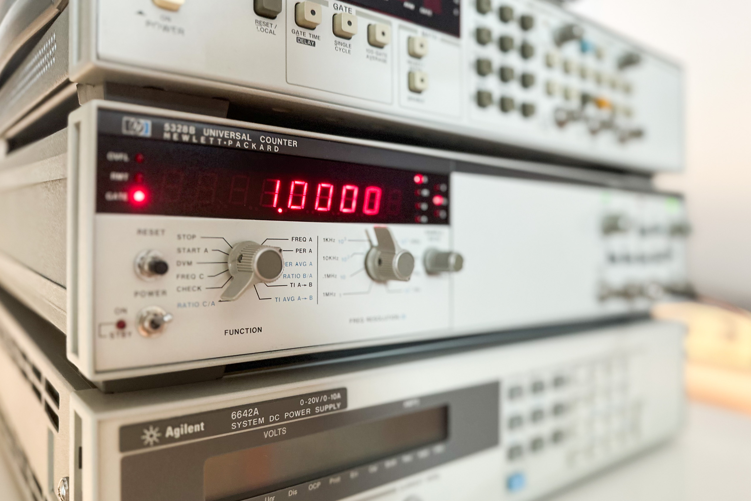
The HP 5328 series counters are a range of 0 to 100 MHz Universal counter from the 70’s. While fairly similar on the outside, internally the updated B model differs from the A model significantly. The HP 5328B’s build quality impresses still today – even for the front panel they didn’t use plastic back then. Its specs however don’t. The direct count measurement provides a resolution of up to 8 digits/s, far less then modern but much more expensive reciprocal counters (with an interpolator) achieve. In my configuration the counter features an 8 digit LED display. In contrast to most newer counters the HP 5328B has dedicated marker outputs (trigger outputs) for each channel on the front panel.

My unit is equipped with an HP-IB interface board. However, it’s missing all options, namely:
- High stability timebase option (opt 010)
- Digital voltmeter option (opt 021)
- C Channel option (1300 MHz) (opt 031)
- Combination of opt 021 and opt 031 (opt 050).
Despite that it consumes a lot of power: Just below 50W when powered on, making a fan obligatory. At about 5W the standby power consumption isn’t all that great either considering opt 010 isn’t installed. However, power consumption is a weak spot on pretty much all frequency counters.
A word of caution: Opening electrical devices can expose you to high voltages that can lead to damage, serious injury or death. If you are not authorized or qualified to work on such devices, don’t do it. This post may not be used as a guide. I don’t take any responsibility for actions you take or the results of these actions. You do everything at your own risk.


Recently I noticed that the 50 Ohm termination of input A didn’t work properly. Although I don’t use this counter very often, I still wanted it to be in full working condition. The culprit was identified quickly. The 50 Ohm termination resistor (51.1 Ohm) was still in spec and the relay’s control signal present. That left the reed relay A12 K2 as the only possible cause.

And so, replacing it by a new Coto reed relay (8L01-05-011) solved the issue. Measurements of the old relay’s contact resistance out of circuit showed fluctuating values.

While I was at it I also replaced some RIFA capacitors and the noisy 110V fan. Conventiently, the unit has a +5V rail that I chose to power the new 5V Noctua fan from. Interestingly this rail is generated by a switching regulator. Didn’t really expect that, but it certainly makes sense. The other rails (+15V and +3.5V) are linearly regulated.
