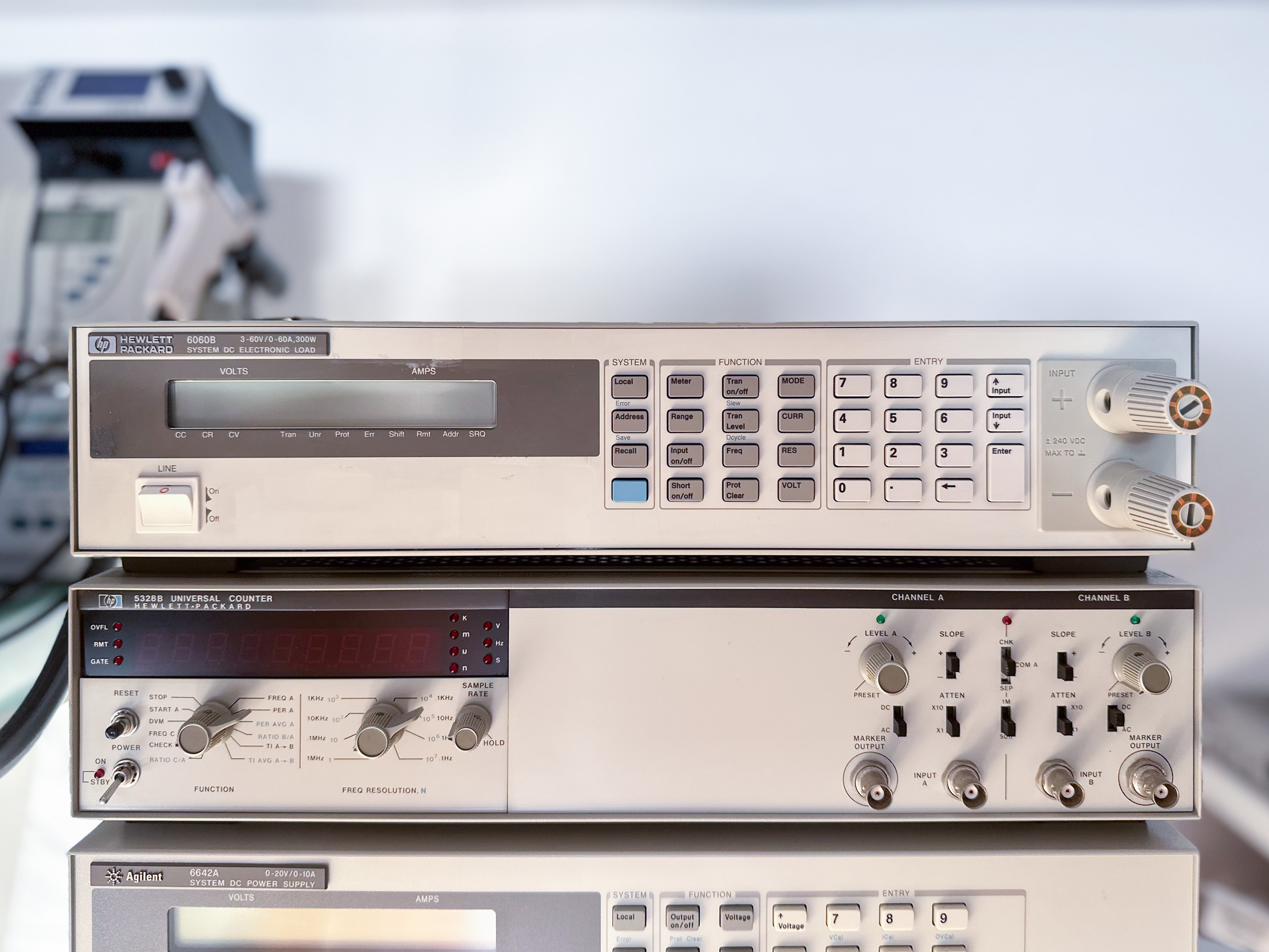
I recently got my hands on a HP 6060B System DC Electronic Load (later also sold as Agilent 6060B). My unit has option 020 installed: Comically large binding posts also on the front panel. This option certainly is not unheard of, but not too common either. Retrofitting is possible, but can be quite some work.

If you’re interested in all the capabilities and specs of the 6060B, I refer to the comprehensive operating and service manuals. That being said, here are some key specs:
- 3 – 60V, 0 – 60A, 300 W
- Constant current, constant voltage and constant resistance modes. Constant power is missing completely, the control loop is purely analog and it would surely be difficult to implement an analog constant power control loop.
- Two current ranges (0-6A, 0-60A), one voltage range (0-60V), three resistance ranges (0.033-1Ω, 1Ω-1kΩ, 10Ω-10kΩ)
My unit was built by HP in 1994 or thereabouts – almost 30 years ago. That means I should have a look inside and do some preventative maintenance.

A look inside
A word of caution: The voltages found inside the unit can cause damage, severe injury or death. If you are not authorized or qualified to work on such devices, don’t do it. I don’t take any responsibility for actions you take or the results of these actions. You do everything at your own risk. Be very careful and stay safe. Any information is provided “as is”.
The first things you’ll see is the large mainboard with a massive heatsink and two transformers. The main board can be devided into four sections: The mains section close to the left edge of the PCB, then the earth-referenced logic right next to that in the upper left area, the mixed-signal and analog control circuits and finally the power stage, wedged in between the analog driving circuits.

The line filter is connected to mains permanently, so it’s even more important to make sure that these filter capacitors are still ok. The voltage selection switches are nicely labeled on the PCB and already set up properly for my location. Interesting to see that HP decided to use two separate transformers instead of only one with just one more winding on it. That gives me a perfect excuse to use two transformers in my own projects – winding transformers isn’t something I’m keen on doing and buying custom transformers gets expensive really fast…


The small transformer (T501) supplies the earth-referenced logic (5V rail), primarily used for the GPIB and user interfaces. Two ribbon cables connect the display and the switch matrix (no separate controller) to the earth-referenced logic. So this design deviates a bit from the System DC Power Supplies with a similar case style, like the 664x series.


The larger transformer (T551) provides power to the floating digital, mixed-signal, analog and power circuits (±15V, +5V rails and fan). You can easily spot the separation of the earth-referenced and floating circuits. Data are exchanged by three optocouplers: Two for the serial transmit and receive lines, the third for a trigger signal.
If we have a look at the mixed signal and analog control circuit we’ll see that it is fairly complex, so much so that I could write a few posts on this part alone. I won’t do that now, but here is a block diagram that gives an overview:

Starting from the left we see three signals: *VMON, *IMON, -10V REF. *VMON is a signal proportional to the voltage at the input, *IMON proportional to the current sunk by the load and -10V REF just a voltage reference. Then there are three DACs. U320 is the main DAC (12-bit). For both the constant current and constant voltage modes the DAC is supplied with a constant reference voltage. In contrast, supplying either *VMON or *IMON as the reference for U320 allows for changing the setpoint continuously and proportional to the input, in a way that the resistance will be constant. Which of both signals and which control loop (CV or CC) is used, depends on the resistance range selected. Transients can be superimposed with the help of transient DAC U321 (8-bit). This DAC is supplied with the same reference as U320. If required an external programming voltage can be superimposed as well.
Then follows the configurable slew rate limiter. With the help of two analog switches its output signal is split into CV_PROG and CC_PROG – the setpoints of the CC/CV control circuits. At its core the CC/CV control circuit uses two separate integrating opamps, U10 for CV and U6 for CC, that are diode-OR’ed together to generate the control variable – the IPROG signal.
Worth mentioning are all the circuits for handling the unregulated state of the DC load (UNREG signal). Let’s say we are in constant current mode and have a current setpoint of 1A, but no supply connected to it, then – without the additional circuits – the control circuit would try to reach the setpoint by switching the FETs in the input stage fully on. If you now connected the supply it would experience pretty much a short circuit – that wouldn’t be good at all, would it?
Of all the protection circuits I found the hardware-over-power protection to be the most fascinating. It’s built around a resistor network R123 (that is fed with both the IMON and the VMON signal) and quad comparator U7. So if you’re curious how they did it, the service manual provides beautiful schematics.

IPROG controls 8 individual power circuits in the input stage. Each of those has its own FET, current sense resistor, current sense amplifier and error amplifier. The outputs of the current sense amplifiers are summed by yet another opamp (U5) giving us the *IMON signal we need for closing the CC control loop.
*VMON, *IMON and two other signals (TEMP; SLEW) are read back with DAC U322 (12-bit) and a quad comparator. There is only one voltage and more importantly one current measurement range. This simplifies the design, but limits the readback resolution and therefore the accuracy in particular for low currents.
Capacitor replacement – the boring part 😉

Like with most HP/Agilent TME of this time, you’ll find a few of the dreaded RIFA line filter capacitors in the 6060B. Those should be replaced without thinking twice. And sure enough, all five RIFA caps show cracks in their cases.

It’s not necessarily the same with the aluminum electrolytics. There is a good chance that those are still fine and will work for a few more years without any trouble – it’s a simple “linear” power supply. And in fact, they measured ok. That being said, I really don’t want to disassemble the unit again any time soon, so they were replaced too.
