With the availability of affordable precision resistors it has become fairly easy to build a diy “resistance standard” that is more than good enough for (most) hobby use cases, e. g. checking DMMs and comparing them with each other. So a while ago I built a simple enclosure for such a precision resistor with 4-Wire (4W) measurement terminals.
2-Wire (2W) measurements are important to me as well, because most handheld DMM don’t feature a 4W measurement. That being said, both their resolution and accuracy are pretty limited, so that I wouldn’t consider the 2W measurement all that critical.
Disclamer right at the start: I did not consider thermal EMF. So you won’t find expensive copper-tellurium binding posts and similar things in this little project. And my precision resistor doesn’t compete with a Fluke 742A resistance standard 😉
Resistors
My practical approach for selecting a resistor was to settle for a certain budget (approx. 30 EUR max.) and then check what options are currently in stock at the usual distributors (like in no particular order Mouser, Digikey, RS components, Farnell and others/local businesses). I aimed for the following specs:
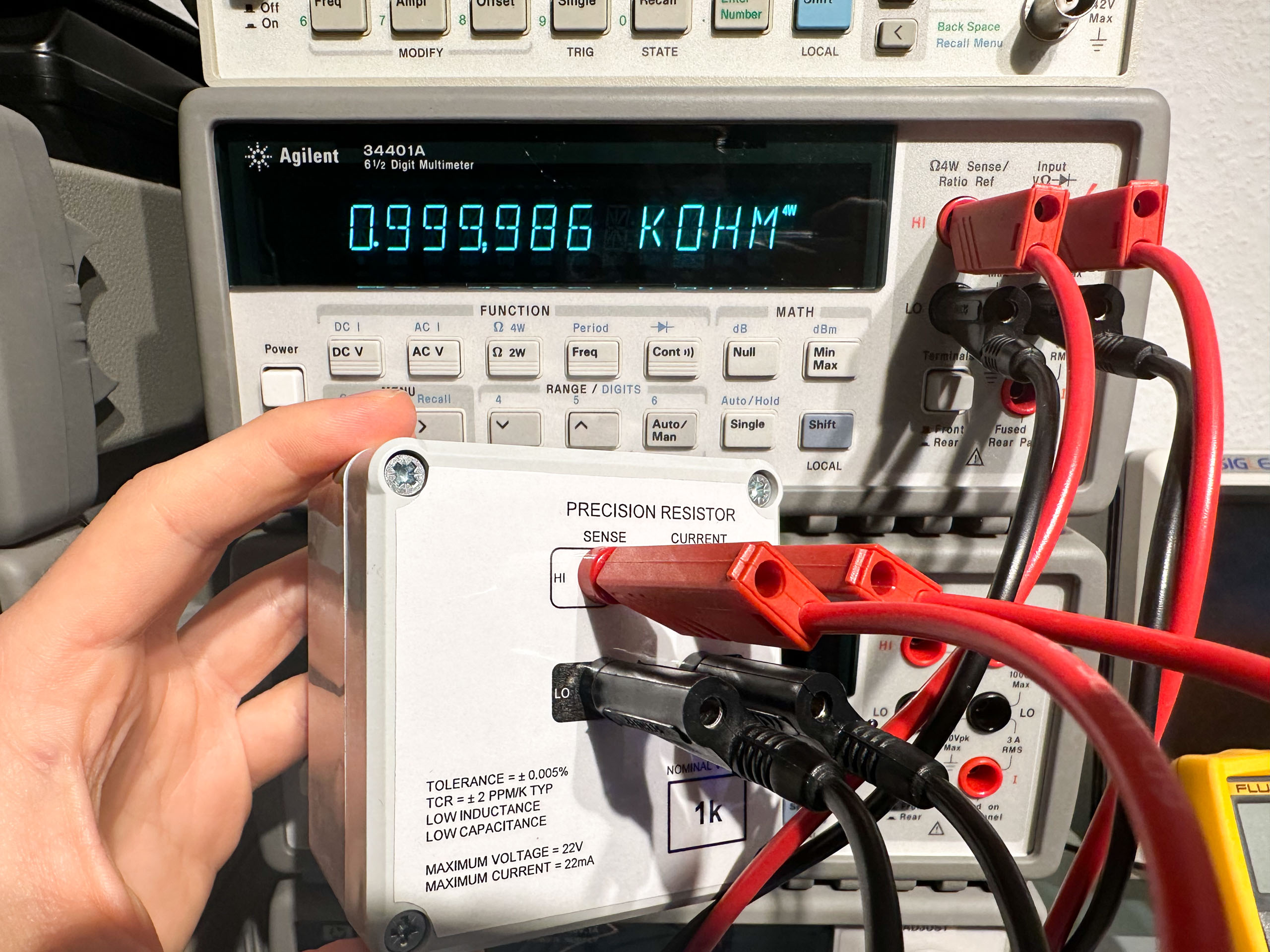
- Nominal resistance: 1k
- Tolerance: 0.005%
- Temperature coefficient: <= 2ppm/K
Internal layout
There are four basic option for connecting the resistor internally:

When running 2W measurements variant b) and d) are optimal, because those reduce the “parasitic” resistance and hence the error introduced by the voltage drop on these wires. (These wires are likely much shorter than the leads connecting the resistor with the DMM, so there won’t be large differences either way).
But what about 4W measurements? I’m not really sure. The additional resistance mentioned above doesn’t matter because of the Kelvin connection. However, variant b) seems to reduce the power dissipation within the device ever so slightly. At the same time, the additional wire in the sense line causes an error that can certainly be neglected: For example, for voltage measurements the input impedance of the HP/Agilent/Keysight 34401A can be selected as either 10MOhm or >10GOhm. During 4W measurements it’s clearly in a high impedance state.
In the end, I think all this doesn’t really matter because of all the other error sources I’m willing to live with/ignore (like temperature coefficent of the resistor or thermal EMF). That leads me to believe that variant b) makes the most sense for me.

Anyway, it’s a good idea to minimize the heat transferred to the resistor during soldering. After closing the (plastic) case we have a finished product:

The following table shows a comparison of a few DMMs and one LCR meter:
| Device | Measurement | Value in kOhm | Deviation in % |
| 1. Agilent 34401A | 4W 2W 2W (Null) | 0.999,981 0.999,995 0.999,983 | -0.0019% -0.0005% -0.0017% |
| 2. Agilent 34401A | 4W 2W 2W (Null) | 1.000,006 1.000,029 1.000,003 | +0.0006% +0.0029% +0.0003% |
| HP 3478A | 4W 2W 2W (Null, manual) | 1.000,19 1.000,33 1.000,19 | +0.019% +0.033% +0.019% |
| Brymen BM789 | 2W 2W (Null) | 0.9998 0.9998 | -0.02% -0.02% |
| Fluke 179 | 2W | 1.000 | +0.0% |
| Keysight U1733C | 2W 2W (open/short) | 1.0000 1.0000 | +0.00% +0.00% |
To put things into perspective: The Agilent 34401A has a 24-hour accuracy specification of 0.0020% of the reading + 0.0005% of the range at 22°C to 24°C. Assuming this spec could be applied in this case (which is not a valid assumption 15 years after the last calibration and at about 18°C ambient temperature), the second meter’s reading could mean any resistance value from 0.999,981 k to 1.000,031 k.
Anyway, I’m happy with the results and plan to add a few other values at some point in the future.