In the last post we discussed how to calculate the power rating of the programmable decade resistor. We assumed that the decade resistor is made of resistors with the same power rating – in reality this might not be the case. Also, it might be a good thing to derate the resistors a bit. So let’s see what the implications are.
Resistor power rating and derating
In this particular implementation, the assumption of equal power ratings of all resistors is only true for the upper five decades-the first decade uses resistors with only \(P_{00} = 0.125 \text{ W}\) instead of \(0.4 \text{ W}\) due to limited availability of higher rated ones. Now the equation looks like this:
$$max(I_{max,1}) = 2 \cdot \sqrt{\frac{P_{00} \cdot\frac{P_{01}}{P_{00}}} {R_{01}}} = 2 \cdot \sqrt{{\frac{P_{00} \cdot \frac{0.4\text{ W}}{0.125\text{ W}}}{10\cdot R_{00}}}}$$
$$=\frac{2\cdot \sqrt{32}}{10} \cdot \sqrt{\frac{P_{00}}{R_{00}}} \approx 1.13 \cdot min(I_{max,0})$$
$$\Longrightarrow max(I_{max,1}) > min(I_{max,0})$$
That’s why we’d have to check the first decade (\(n = 0\)) as well, whenever the second decade (\(m = 1\)) is the highest non-zero decade.
Derating of the resistors
There is another aspect that might actually help us out: Derating. It’s a good idea to derate the resistors. This not only limits the temperature and therefore improves stability, but also gives some additional headroom for an accidental overcurrent situation.
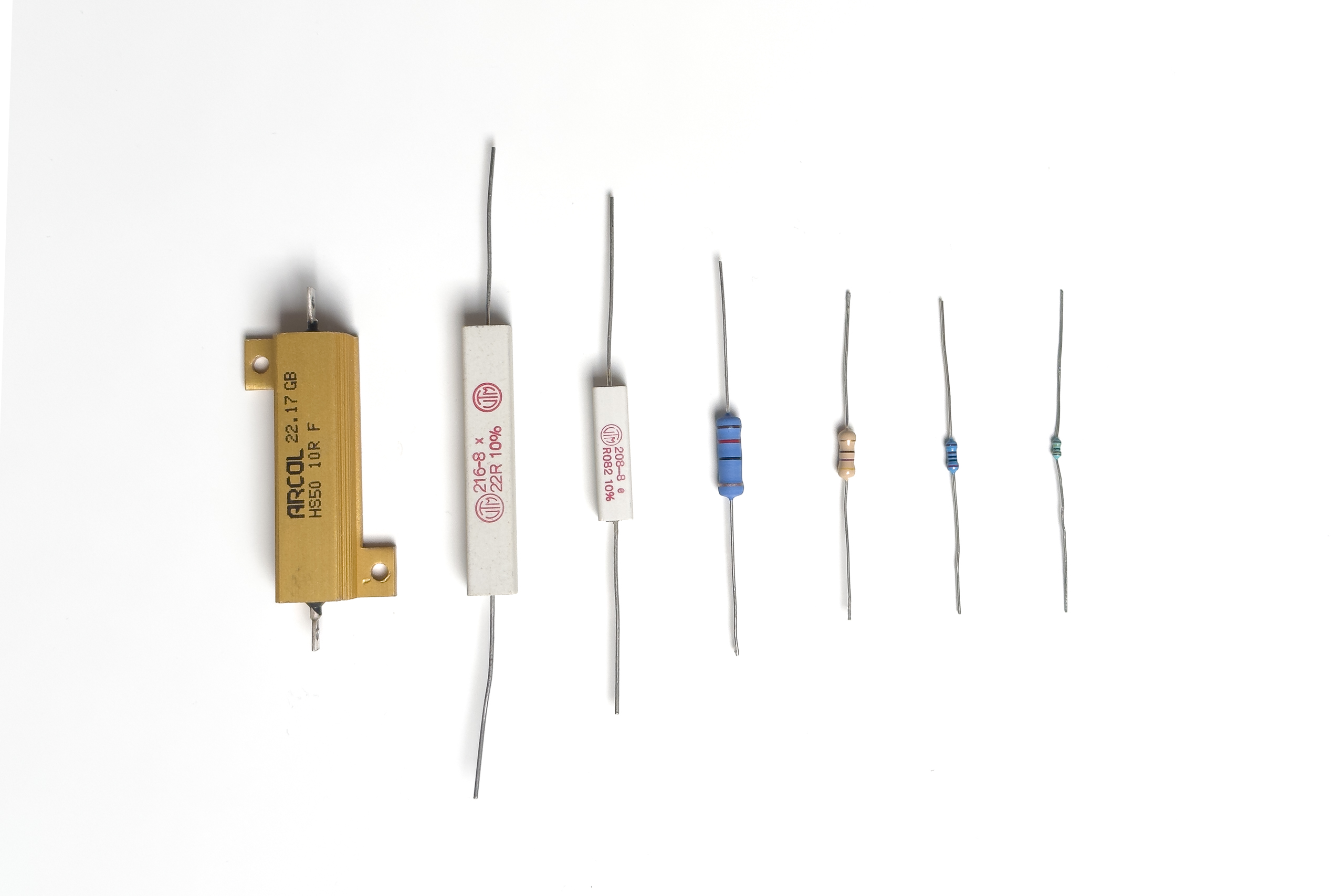
The initial requirement for the programmable resistor was a power rating of \(P_{max,tot} \ge 0.5 \text{ W}\) for all ranges. Since the power rating of a single decade is \(P_{max,n} \ge 2 P_{0n}\) (see table for a single decade), we can derate the resistors from \(0.4 \text{ W}\) to \(0.25 \text{ W}\) (-37.5%) for all decades \(n \ge 1\) without compromising the goal.
Not so great: The first decade has to use \(0.125 \text{ W}\) resistors, making it impossible to achieve anything close to the initial goal, even without any derating. So would it at least be possible not to limit the maximum current even more than the second decade does, while still allowing for some derating? Yes, with a derating to \(0.1 \text{ W}\) (-20%) we get:
$$max(I_{max,1}) = 2 \cdot \sqrt{\frac{P_{00} \cdot\frac{P_{01}}{P_{00}}} {R_{01}}} = 2 \cdot \sqrt{{\frac{\frac{0.25\text{ W}}{0.1\text{ W}} \cdot P_{00}}{10\cdot R_{00}}}}$$
$$= \frac{2\cdot \sqrt{25}}{10} \cdot \sqrt{\frac{P_{00}}{R_{00}}} = min(I_{max,0})$$
So no special checks for the first decade required anymore. Summed up:
| Decade \(n\) | Resistor Power Rating \(P_{0n}/\text{ W}\) | Derated resistor power rating \(P_{0n,d}/\text{ W}\) | Decade Power Rating \(P_{max,n}/\text{ W}\) |
|---|---|---|---|
| \(0\) | \(0.125\) | \(0.1\) | \(\ge 0.2\) |
| \(1 … 5\) | \(0.4\) | \(0.25\) | \(\ge 0.5\) |
Calculation of the limits
After all those considerations it’s fairly simple to calculate the current, voltage and power limits:
- Determine the maximum allowable current:
It’s trivial to determine the highest decade \(h\) that is not shorted. Therefore, the maximum current \(I_{max,tot}\) can be determined easily (see table for single decade in part 1). - Calculate the maximum allowable voltage:
$$U_{max,tot} = R \cdot I_{max,tot}$$ - Calculate maximum allowable power dissipation
$$P_{max,tot} = R \cdot I_{max,tot}^2$$
There might be other reasons to limit the current, voltage or power. A good example would be voltage limits imposed by the PCB’s clearance/creepage distance between conductors of different potential.
In the next posts in this series will dive into the topic of relay switching.