Category: Programmable Decade Resistor
-
Programmable Decade Resistor: Cost
I didn’t really think about the BOM cost of my programmable decade resistor until I was asked. Then I also wanted to know. It is fairly difficult to put a number to what I paid, since I had a lot of components left from other projects that I could use. This includes not only cheap…
-
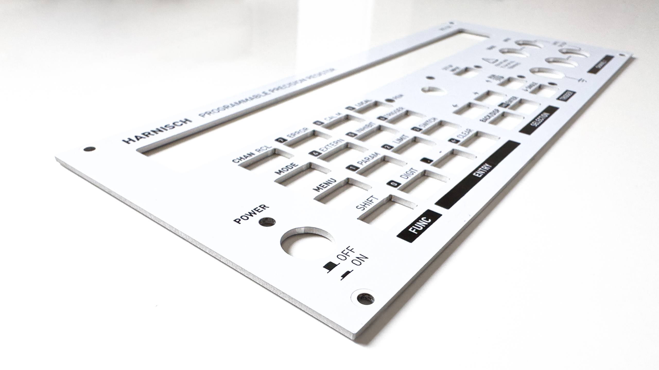
Programmable Decade Resistor: Panels
I was asked a few times how I did the front and rear panels, so this is what I’d like to talk about in this blog. There are different ways to achieve a similar result. For me, the easiest and most cost-effective solution was to just design another PCB – I know how KiCAD works…
-
Programmable Decade Resistor: Components
After being asked about some aspects of the mechanical design and components used a few times, I’d like to address those questions. I have to admit that I’m neither very good at the mechanical design, nor do I have a 3d printer (yet) or a shop where I can do metal work myself. That being…
-
Programmable Decade Resistor: Improved results
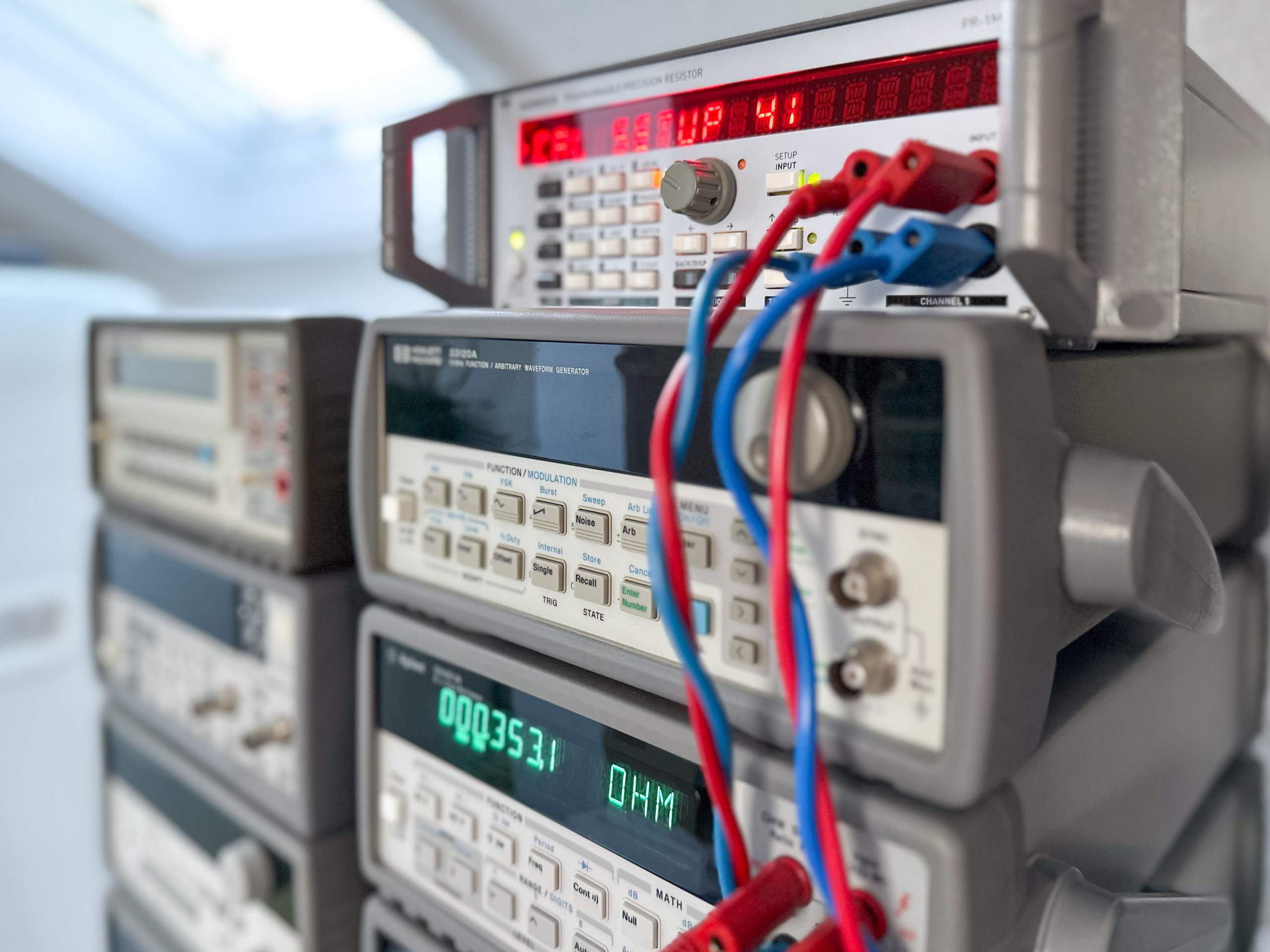
After the modification described in the previous post I let the the “adjustment”/calibration procedure run again. Five days later I repeated the calibration (not the adjustment). As before, all measurements are performed with an Agilent 34401A 6.5 digit multimeter. Accuracy of the resistance First up is a diagram that shows the absolute value of the…
-
Programmable Decade Resistor: Optimization
I went into this project with the thought that it will be a rather small one. This certainly influenced some decisions I made along the way. Now that the project had evolved into a much larger thing than initially anticipated it’s reasonable to have another look at possible optimizations, albiet the calibration results were already…
-
Progammable Decade Resistor: Calibration results
In one of the previous posts I covered in depth, how I use the term “calibration” in the context of the programmable decade resistor and how the calibration procedure works. Today it’s all about the result. Also, I’d like to mention the first post in which I defined a rather loose accuracy goal of \(\ll\pm…
-
Programmable Decade Resistor: Warm-up curve
Generally, test and measurement equipment needs a certain period of warm-up time to provide low drift. That is also true for the programmable decade. I’m especially interested in the warm-up time with all relays off as well as with many relays on. I chose a value of \(100\text{ k}\Omega\) for the second test. (For simplicity…
-
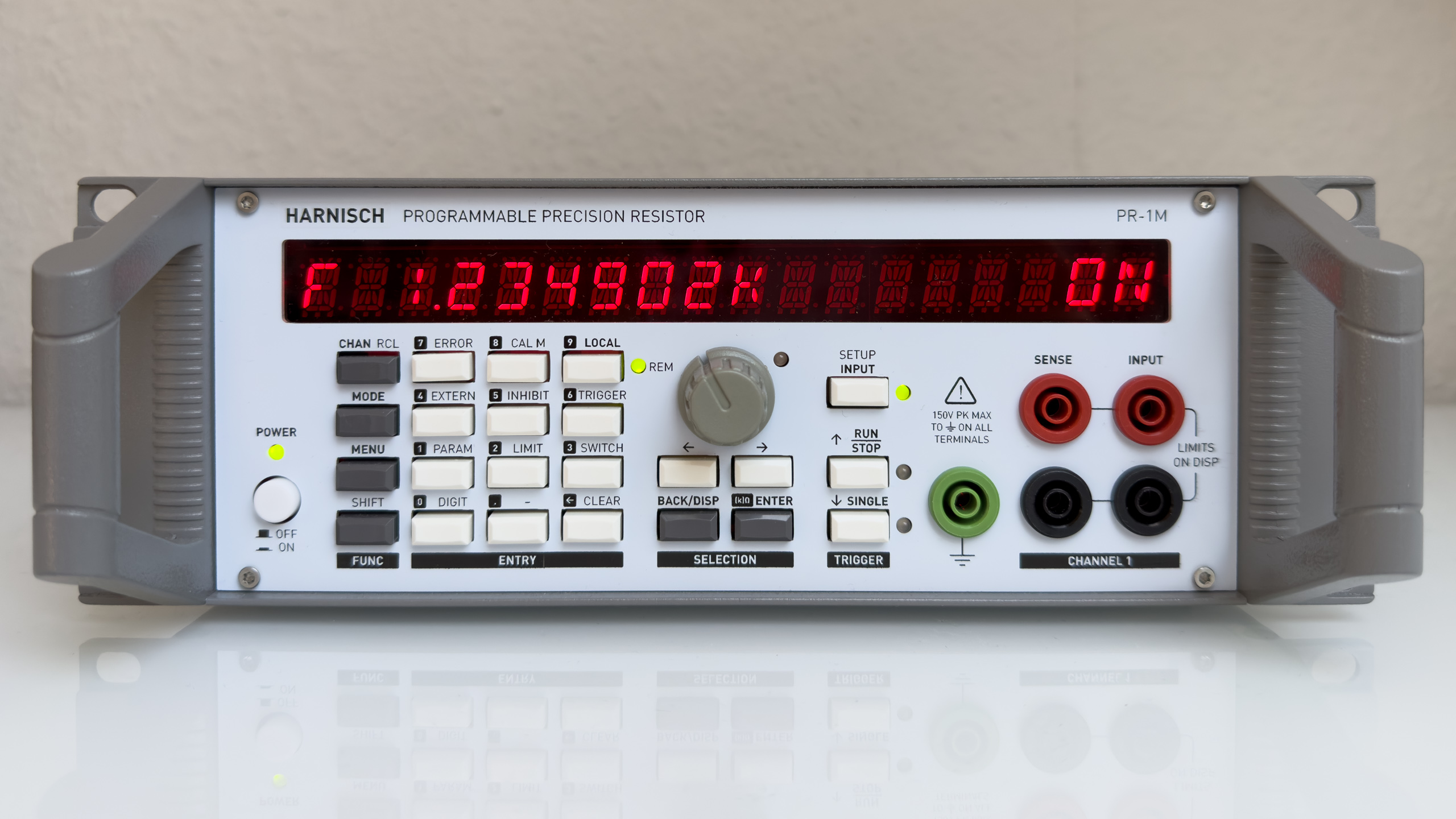
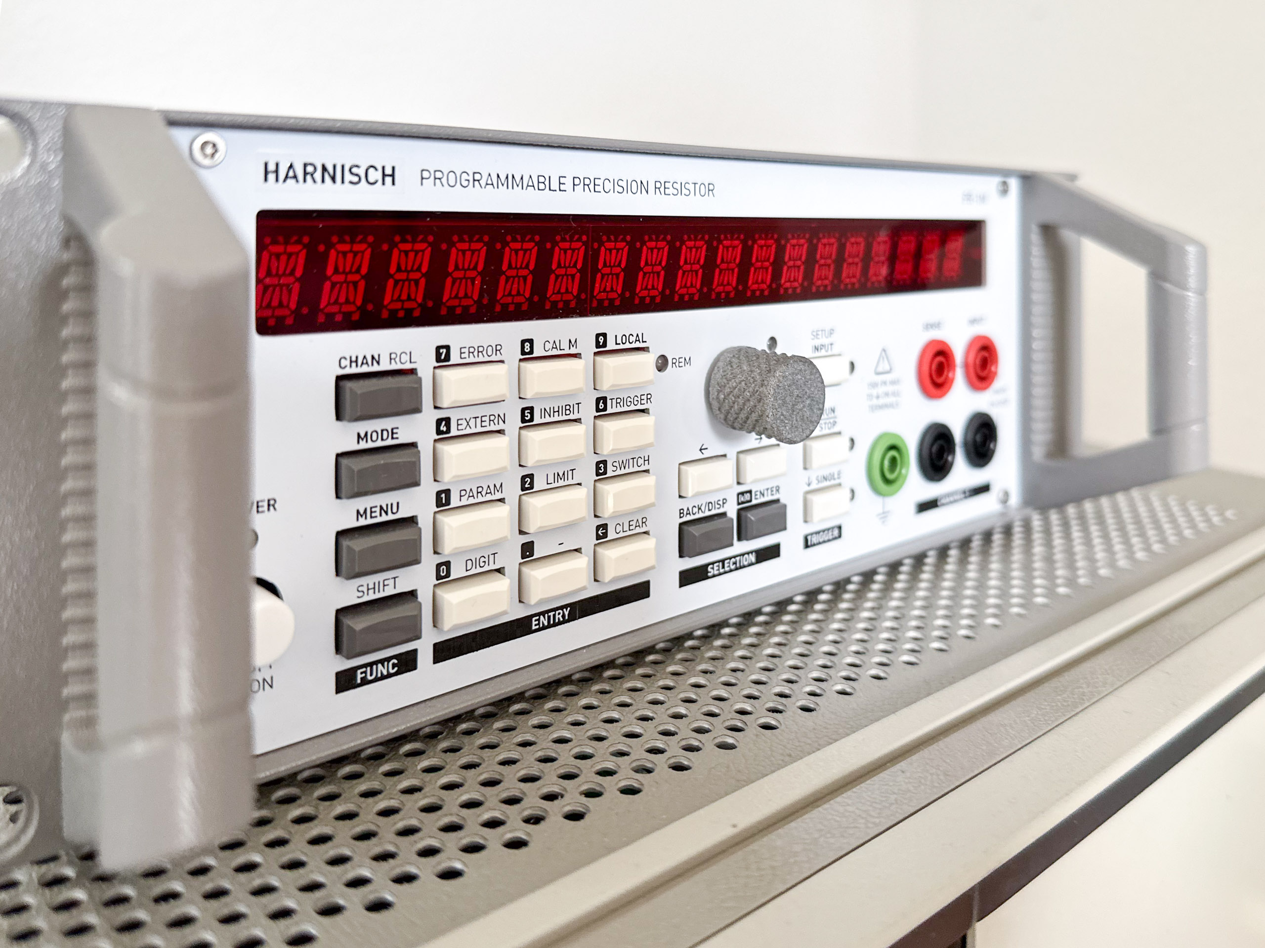
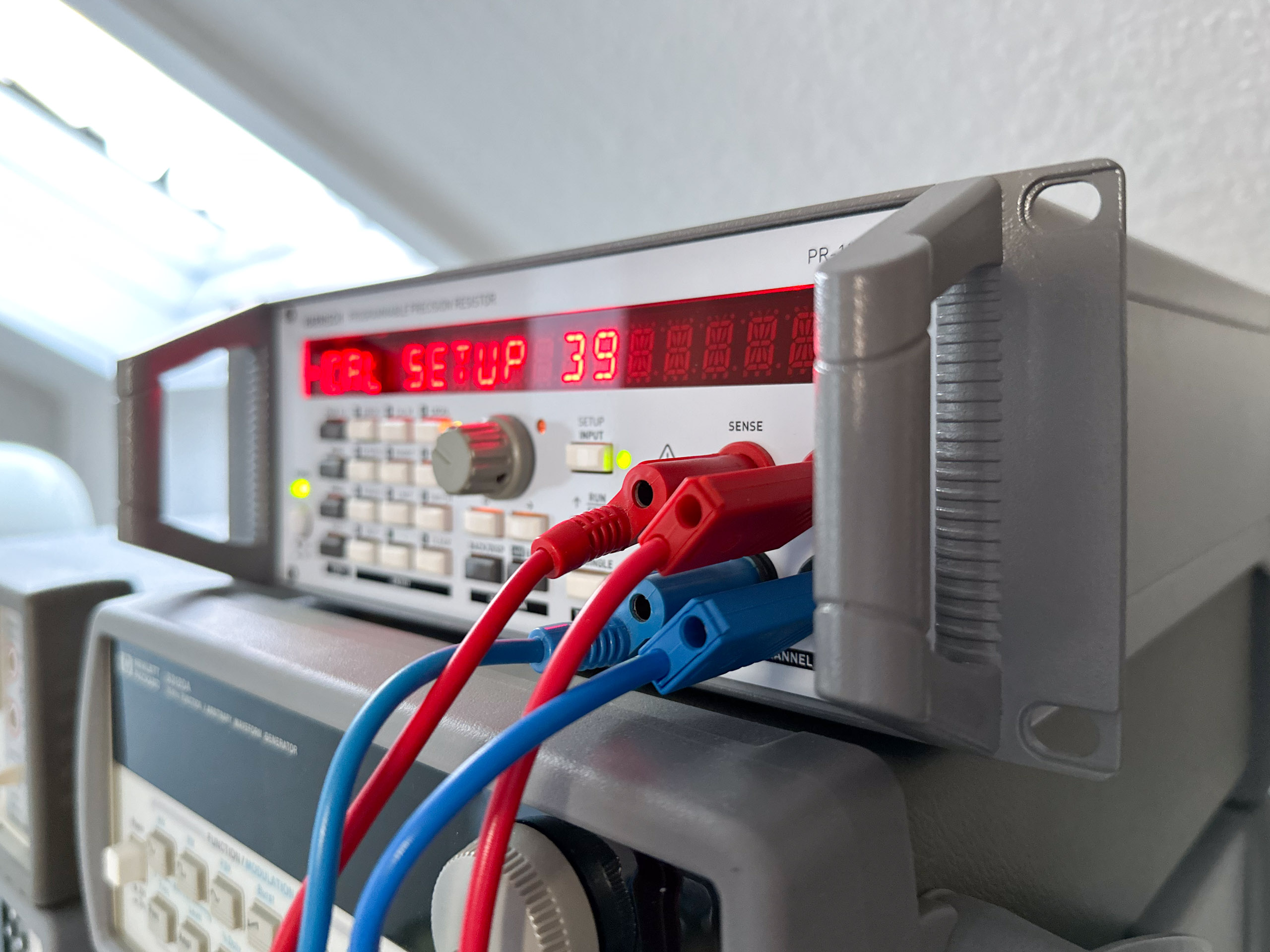
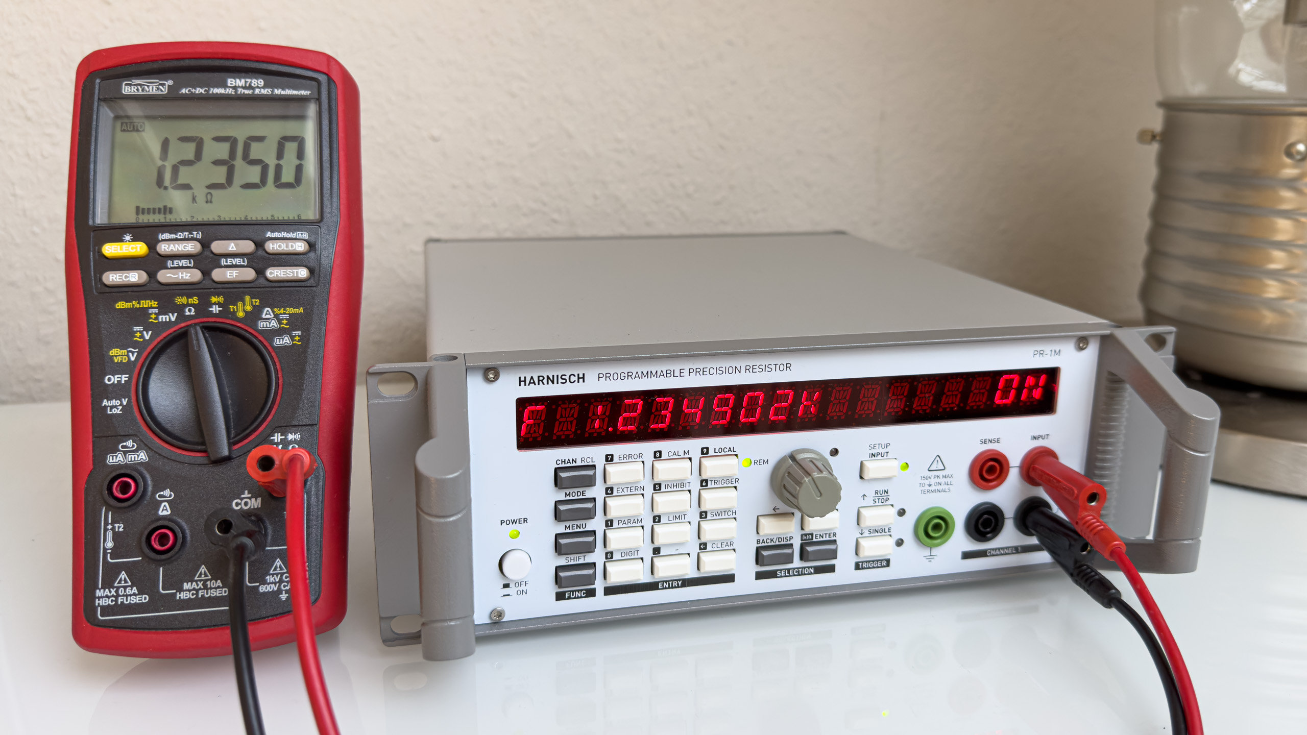
Programmable Decade Resistor: Final Product
In this post I’ll show a few pictures of the programmable decade resistor in its enclosure.
-
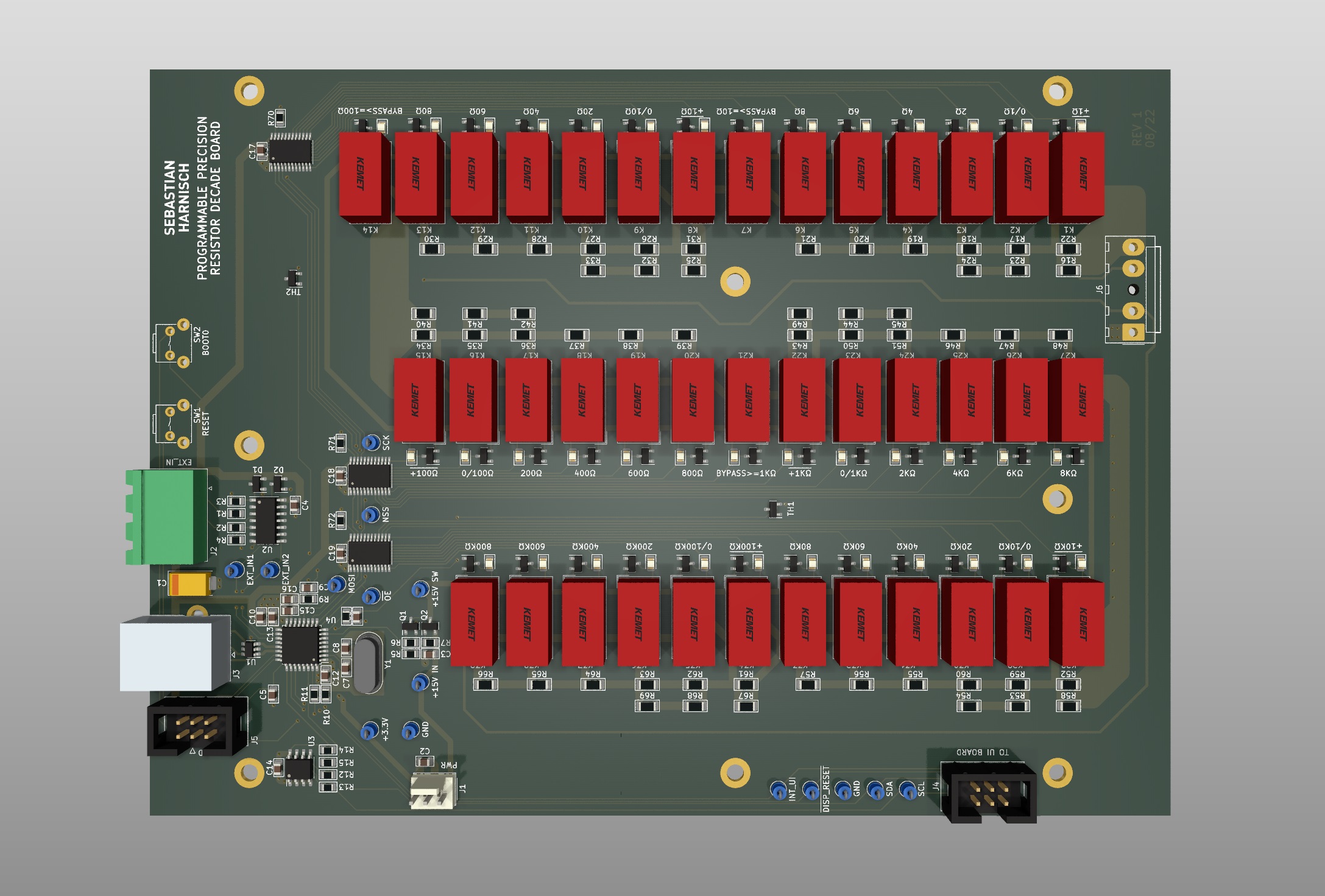
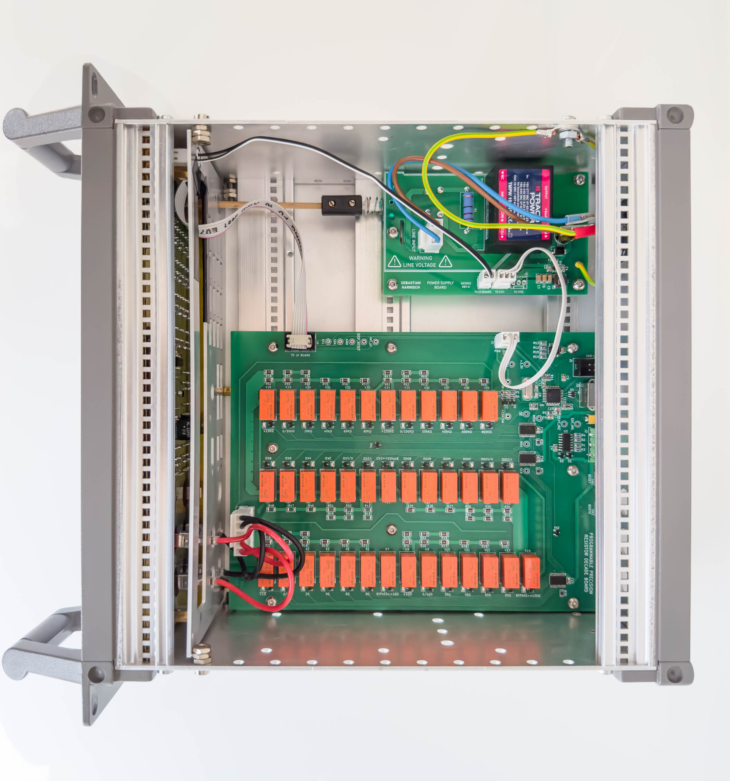
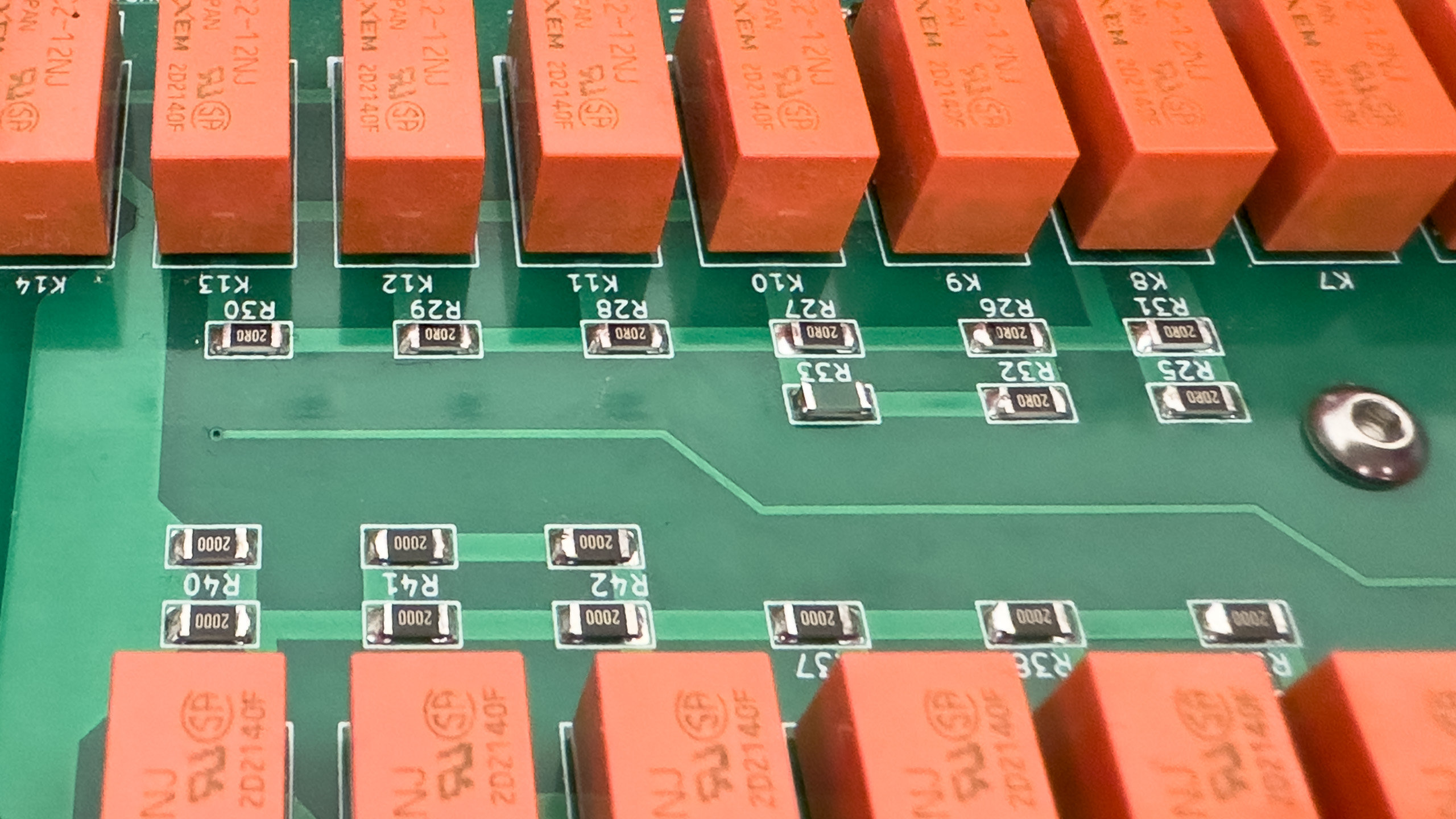
Programmable Decade Resistor: Mainboard
The mainboard features the main controller paired with an EEPROM, the resistor decades (precision resistors, signal relays) including two temperature sensors, relay drivers and signal conditioning for the two external digital inputs. Main controller The main controller is a STM32G441KBT6 microcontroller (170MHz Cortex M4, 128kB Flash, 32kB RAM). The microcontroller features a USB 2.0 device…