Although the Programmable Power Resistor re-uses some components, many design ideas and a good portion of the software of the Programmable Decade Resistor (Programmable Precision Resistor), there were many changes and also some improvements regarding some aspects of the mechanical construction and the code.

Features and specs
So now it’s time to present the feature list/specs:
| Parameter | Value/Description |
|---|---|
| Resistance range (nominal, \(\Omega\)) | short circuit, 1.25 to 80 , open circuit: 0, 1.25, 1.429, 1.538, 1.667, 1.818, 2, 2.143, 2.222, 2.273, 2.308, 2.353, 2.5, 2.727, 2.857, 2.941, 3, 3.077, 3.158, 3.333, 3.448, 3.529, 3.636, 3.750, 4, 4.167, 4.286, 4.444, 4.615, 5, 5.263, 5.455, 5.714, 5.833, 6, 6.5, 6.667, 7.143, 7.333, 7.5, 8, 8.333, 8.571, 9, 9.167, 9.375, 10, 10.667, 10.909, 11.111, 11.667, 12, 12.5, 13.333, 13.636, 14, 15, 15.385, 16.667, 17.143, 17.5, 18.333, 19, 20, 21.667, 22.5, 23.333, 24, 25, 26.667, 27.5, 28.333, 29, 30, 31.667, 32.5, 33.333, 34, 35, 36.667, 40, 42.5, 43.333, 44, 45, 46.667, 50, 55, 60, 65, 70, 80 |
| Setpoint resolution | settable to \(1 \text{m}\Omega\), selects closest supported resistance value |
| Short-term setpoint accuracy estimate | \(\le \pm 1\% \text{ of nominal value} + 0.2 \Omega\) |
| Display resolution | three decimal places (fixed) |
| Thermal drift (estimate based on design) | \(50 \text{ppm}/\text{K}\) |
| Power/current rating | Depends on resistance setting. Limiting values are calculated and displayed. Up to ~150 W continuous (400W peak) or 6A, whichever is lower (preliminary) |
| Bandwidth | unspecified |
| Calibration modes | – Uncalibrated: Switches are activated according to entered setpoint, display shows setpoint – Two-wire (2W), Four-wire (4W): The resistance value closest to the entered setpoint is selected |
| Operating modes | Fixed: On trigger, no change Step: On trigger, step to trigger setpoint value Up: On trigger, increase setpoint (auto, linearly, 1-2-3-4-5-6-7-8-9, 1-2-5, 1-3) Down: On trigger, decrease setpoint (linearly, 1-2-3-4-5-6-7-8-9, 1-2-5, 1-3) List: See list mode |
| List mode | Up to 100 values with individual dwell times – Start: on trigger; or immediately after mode selection – Step: – Auto: Advance index automatically, solely based on dwell time – Trigger: Advance index on each trigger event, ignoring the dwell time – Once: Advance index on each trigger event, only after dwell time elapsed |
| Switching | – fast (default) – break-before-make |
| Protection | Over temperature protection (OTP) |
| Trigger | Source: Bus, Immediate, Manual, Timer Mode: Continuous, Single Parameter: – Delay, – Holdoff, – Time (0.01 s .. 10^7 s; Source: Timer) |
| Command and trigger execution | 10ms loops |
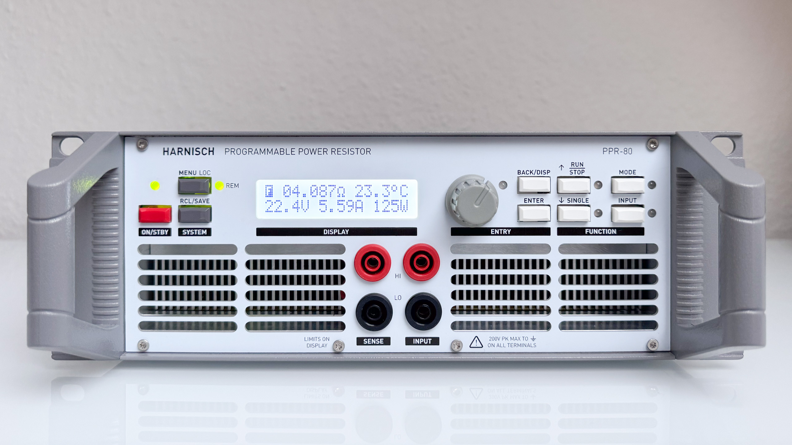
| User interface | – 16×2 Dot Matrix display: – Primary display: Resistance setpoint, (max.) heatsink temp. – Secondary display: – limiting values (voltage, current, power) – trigger state – uncalibrated resistance value |
| User presets | 0-9 (0 is restored on power-up) |
| Interface | – Input and Sense: 4mm safety banana jacks – USB (Virtual COM port) |
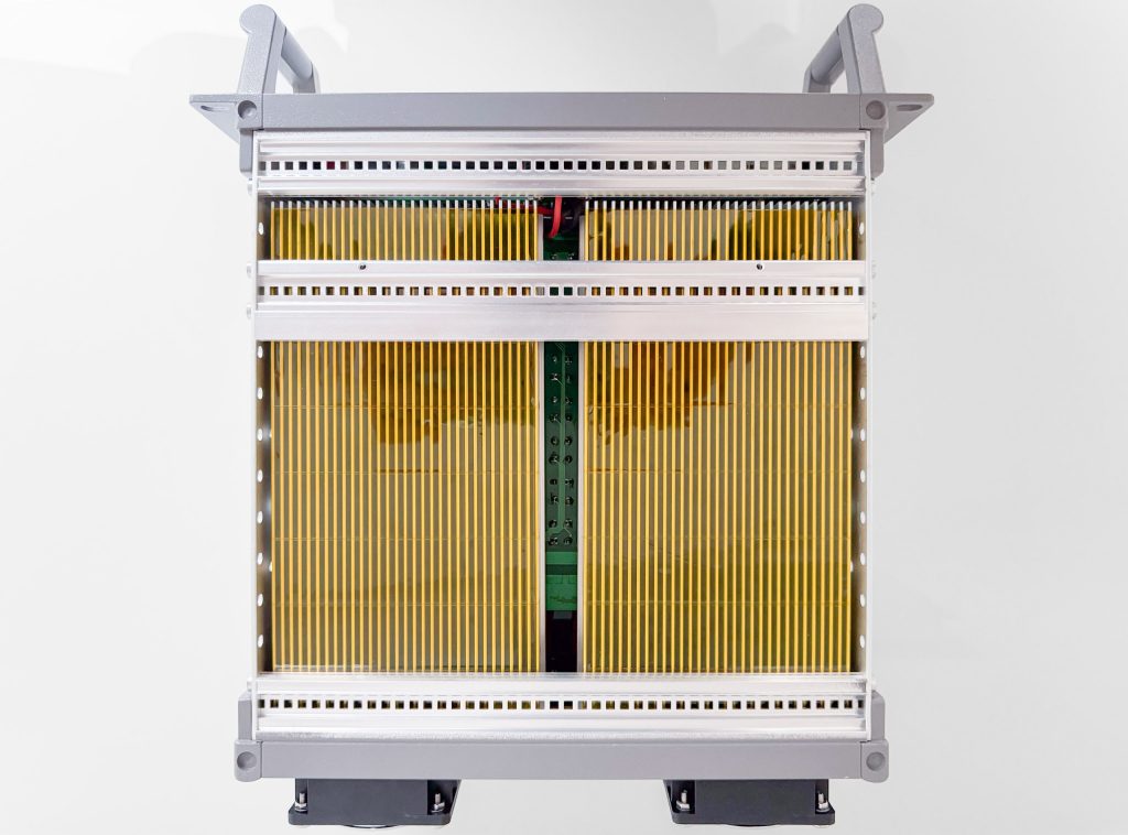
| Fans | Two temperature controlled 60mm fans (12V, 4500 rpm) |
| Power supply | Switch mode |
A look inside
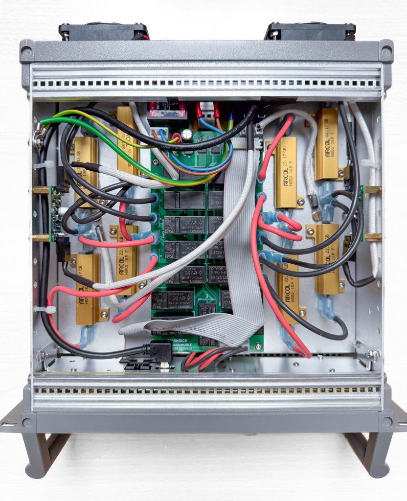
Looking at the rats-nest of wires, it’s clearly a revision A… Some of it is a product of the small case – with more board space it would have been easier to place the connectors a bit better. Then I decided to use different, more powerful fans than planned initially and those do not have a PWM input. This explains the two small “pwm-to-voltage converter modules”, one on each side of the case.
Also, I could have done a better job managing all the cables, and possibly connecting the resistors in a way that minimizes cable length (or alternatively distributing the heat across the heatsink as evenly as possible depending on the switching state). But “good enough” has to suffice…
For now, I don’t think I need a second unit. In case that changes, I have some ideas for a second revision with some minor improvements and adaptations (like integrating the pwm-to-voltage circuits), but also one new feature: A simple voltage measurement. This not only allows for a handy display of the voltage, current and power, but also additional fan control options and protection features.