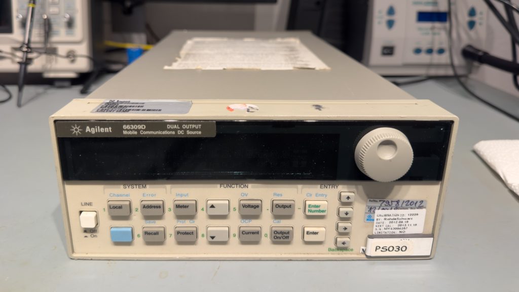
A few days ago I got my hands on a faulty Agilent 66309D Mobile Communication DC Source. To be honest, I don’t think I need it, but it was pretty cheap and I was looking for something to either repair or potentially salvage the case of.
The Mobile Communication DC Source is a specialized power supply. It not only has an improved transient response, but also a few other features not found on standard power supplies (e. g. E363x, E364x). The list for the Agilent 66309D includes (not necessarily exhaustive):
- Downprogrammer for sinking currents (it’s not a DC load, doesn’t track the current setpoint)
- Two current measurement ranges
- Some DSP capability for enhanced measurement functions (e. g. RMS current)
- Separate DVM (Digital Volt Meter)
- secondary output (likely meant to simulate a battery charger)
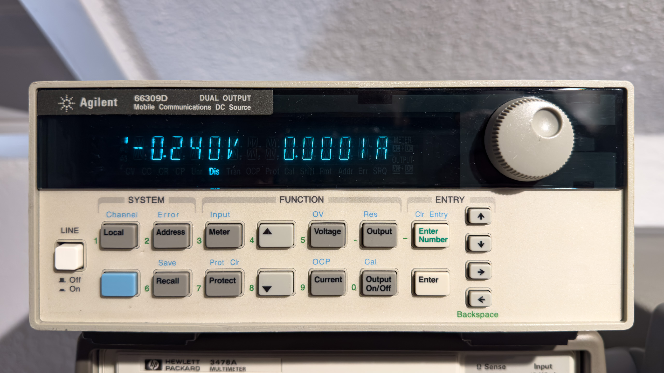
The user interface differs from Agilent’s power supplies of the era too: It allows for entering numeric values for setpoints through labeled buttons instead of just relying on the rotary encoder – for many applications I favor this approach – very often I just want to enter 3.3V, 5V or 12V and be done with it.
As far as I can tell Agilent/Keysight decided to not publish the full schematics of the unit (I haven’t really seen an older service manual with schematics – it might be out there somewhere, please let me know if it is). Instead the service manual has simplified diagrams/schematics. Certainly a step in the wrong direction for electronics enthusiast like myself, on the other hand I understand this decision.
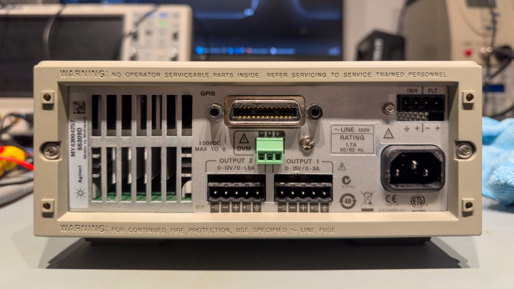
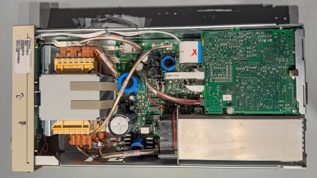
Only after buying the unit I noticed the 120V sticker and was wondering whether someone had powered it from 230V, potentially destroying close to everything in it. I was relieved to see that the unit can be converted to 230V operation and – after opening it – that this conversion actually had been done.
Since I knew that my unit was faulty I didn’t power it up, instead I looked for obvious problems. One issue was found very quickly: The so called “+5V GPIB bias fuse” was blown. This name was poorly chosen though, because in reality the rail also supplies some of the earth-referenced power supply logic beyond the GPIB capability. In fact, the user interface board is connected to the “GPIB board”, if one wanted to call it that way. The really strange thing though: I couldn’t find any short circuit or damaged component.*
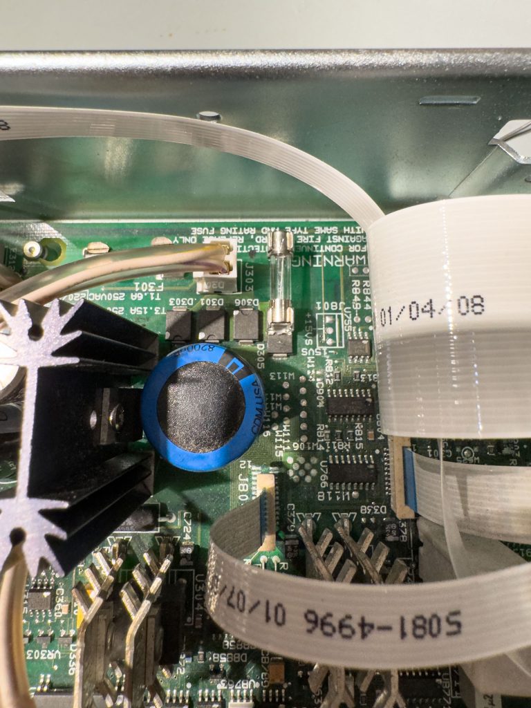
So I powered the unit through my AC source/analyzer, ramping up the voltage slowly just to be sure. And as expected no excessive current flow at all, the transformer hums, but no display, nothing… That is were I supplied the rail with a bench power supply with the current limit set to 1A – well below the fuse’s 5A. Without any further issues the power supply turned on, drawing just above 500mA. Seems reasonable for a lot of logic ICs including the GPIB controller, I think. All further tests were positive, including the general operation of both channels as well as the remote control via GPIB. So a fuse replacement (only 2A, should be plenty) later the unit seems to be up and running again. Why would a 5A fuse blow without any obvious catastrophic failure? Was that a simple component failure of the fuse or is there anything else going on? Time might tell.
* obviously a component could become open after a fault, but since everything (and in particular everything logic-related) seems to work properly I’m not sure which component that would be. Haven’t found any burned component and I looked for it.