After being asked about some aspects of the mechanical design and components used a few times, I’d like to address those questions. I have to admit that I’m neither very good at the mechanical design, nor do I have a 3d printer (yet) or a shop where I can do metal work myself. That being said, I was still able to design a reasonably professional looking device and bring it to life with the help of modern prototyping services.
| Component | Manufacturer/Product | Note |
|---|---|---|
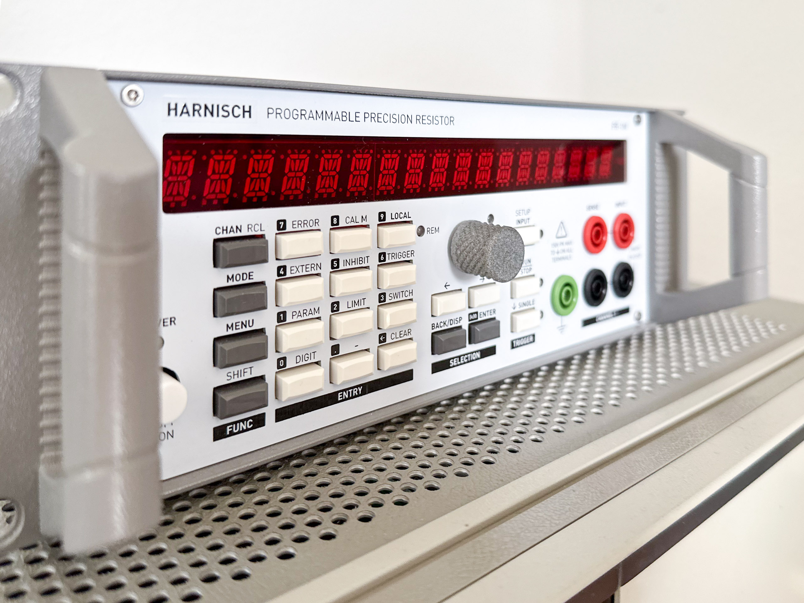
| Case | ELMA, Stylebox 15 Standard; 2 RU, 42HP (half 19″) | Probably fairly expensive when bought new |
| Front/Rear panels | 1.6mm Aluminium PCB with white solder mask and black silk screen | Didn’t want to have a conductor left floating (potentially), so I removed the copper |
| New Rotary knob | 3d printed (MJF) | Most pictures were taken with the old temporary knob |
| Push buttons | C&K/littlefuse PVA series switches with matching caps | Different force ratings available |
| Line switch | C&K NE18 series switch | Can be a pain in the *** to design and print a connecting rod if the switch is located far back in the unit. I just used a thin wood rod and some tiny shaft coupling to connect the rod with the switch. Seems to work just fine. A 3d printed part would be more professional, no doubt about it |
| Red filter for display | Color filter, Red foil, 0.3mm; random amazon product; glued to the back of the front panel | Works surprisingly well, however it’s obviously not as strong as acrylic glas. Reminds me of the HP/Agilent 66xx series power supplies (and other products) with the thin foil covering their LCD displays. Wouldn’t like that for commercial use 😉 |
There will be a separate post where I explain the fairly straight forward process of designing the front and rear panels.