20230714_190902745_iOS

Progammable Decade Resistor: Calibration results

In one of the previous I covered in depth, how I use the term “calibration” in the context of the programmable decade resistor and how the calibration procedure works. Today it’s all about the result. Also, I’d like to mention the first post of this series in which I defined a rather loose accuracy goal of ≪±0.5% of value+0.3Ω\ll\pm 0.5\% \textrm{ of value} + 0.3 \Omega. In reality, I expect the device to be much, much better than this. Nevertheless, I will still compare the results to these limits. ...

July 15, 2023 Â· 7 min Â· Sebastian
20230617_155717412_iOS

Programmable Decade Resistor: Warm-up curve

Generally, test and measurement equipment needs a certain period of warm-up time to provide low drift. That is also true for the programmable decade. I’m especially interested in the warm-up time with all relays off as well as with many relays on. I chose a value of 100 kΩ100\text{ k}\Omega for the second test. (For simplicity I decided against using latching relays, however that would be a better choice performance-wise as mentioned before. Due to the additional power dissipation in the relay coils the curves will look different.) ...

July 7, 2023 Â· 3 min Â· Sebastian
20230617_155356512_iOS

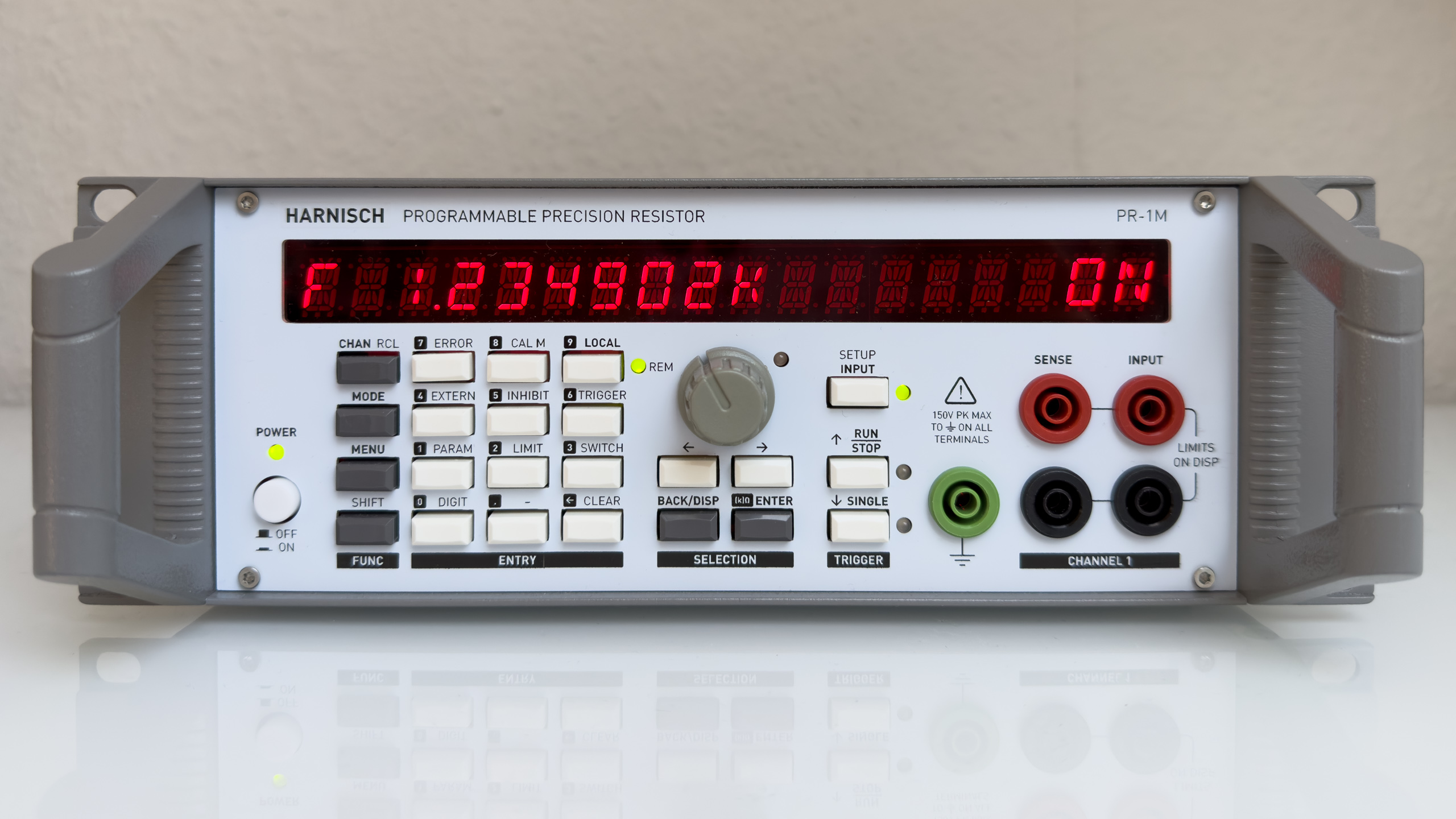
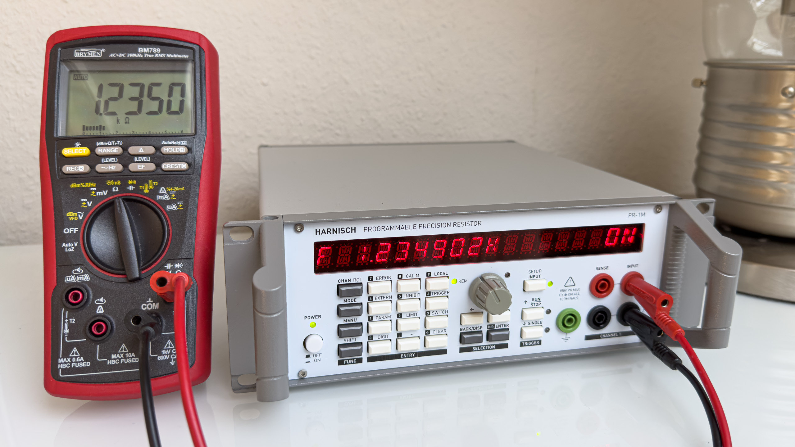
Programmable Decade Resistor: Final Product

In this post I’ll show a few pictures of the programmable decade resistor in its enclosure. Inside the unit Mainboard with some powered relays Rear panel: Optional terminals for channel 2, digital inputs, USB, power and fuse Unit with the case closed ...

June 23, 2023 Â· 1 min Â· Sebastian
mainboard_ausschnitt

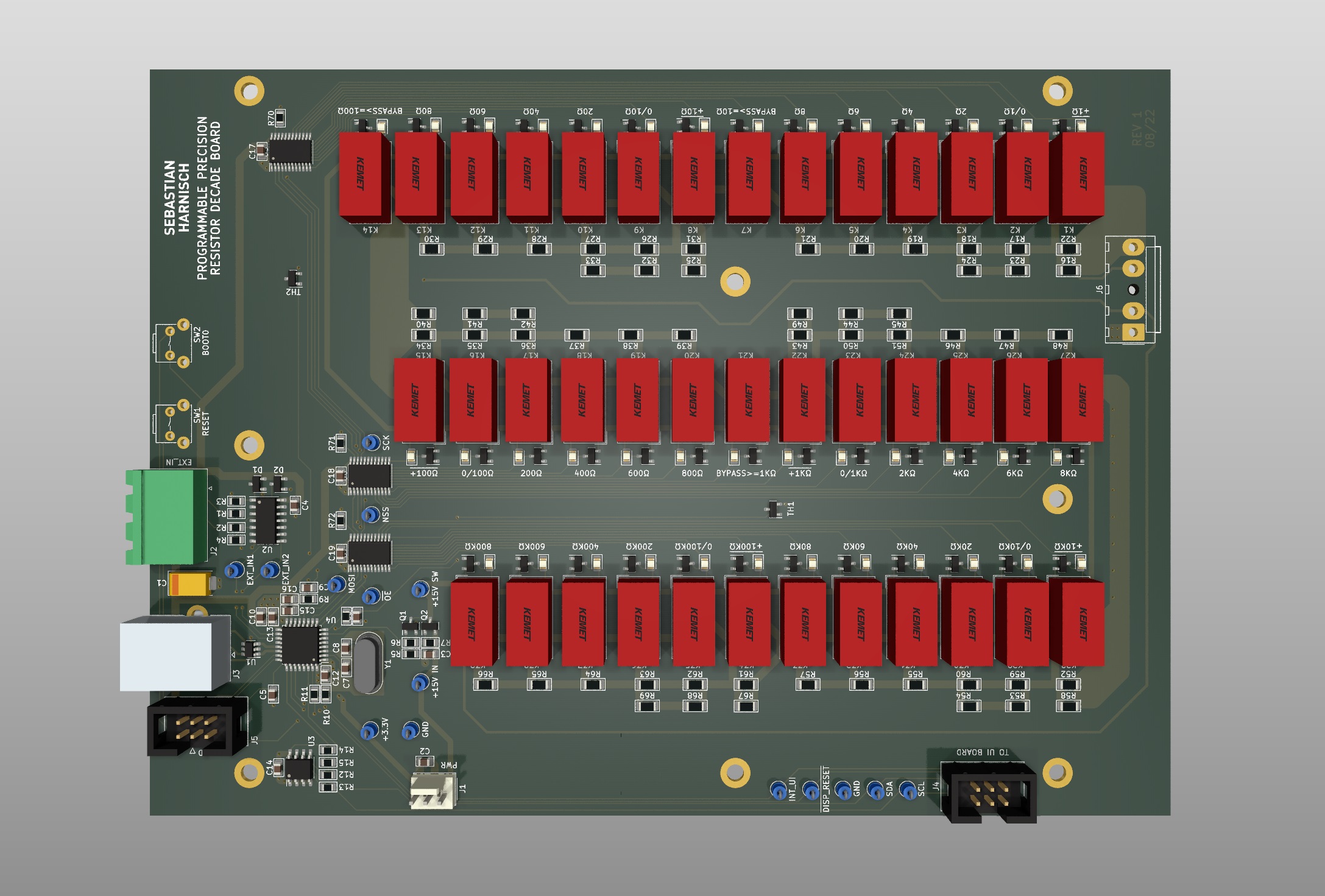
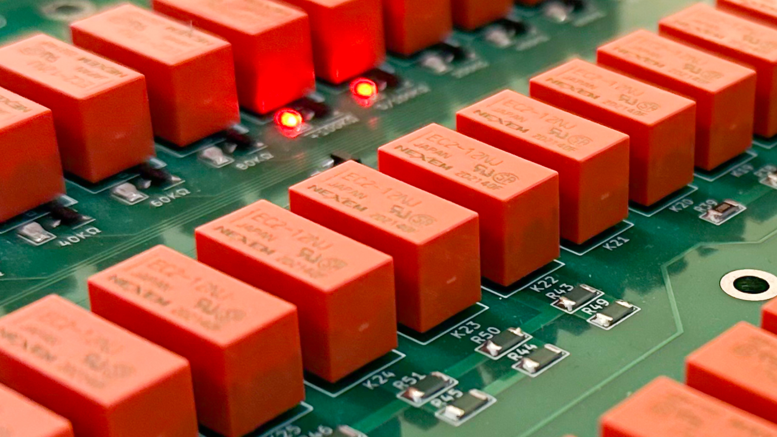
Programmable Decade Resistor: Mainboard

The mainboard features the main controller paired with an EEPROM, the resistor decades (precision resistors, signal relays) including two temperature sensors, relay drivers and signal conditioning for the two external digital inputs. Main controller The main controller is a STM32G441KBT6 microcontroller (170MHz Cortex M4, 128kB Flash, 32kB RAM). The microcontroller features a USB 2.0 device peripheral. The main controller contains the business logic required to control the relays and provide a user interface. It handles the processing of user user inputs, originating from either the mentioned user interface board, from SCPI messages sent over USB (virtual COM port) or from the external digital inputs. ...

June 14, 2023 Â· 3 min Â· Sebastian
20230602_153929609_iOS

Breakout box for Agilent 6611B AC Power Source

I got my Agilent 6611B AC power source/analyzer a few weeks back, but hadn’t used it as much as I wanted. The reason was simple: The connections are made with rear mounted screw terminals - hence it was just a bit inconvenient to interface with products and circuits. The solution was really simple: A Hammond Manufactoring enclosure equipped with a European " Schuko"-style power outlet and some additional safety-banana jacks for prototyping. ...

June 7, 2023 Â· 2 min Â· Sebastian
block_diagram

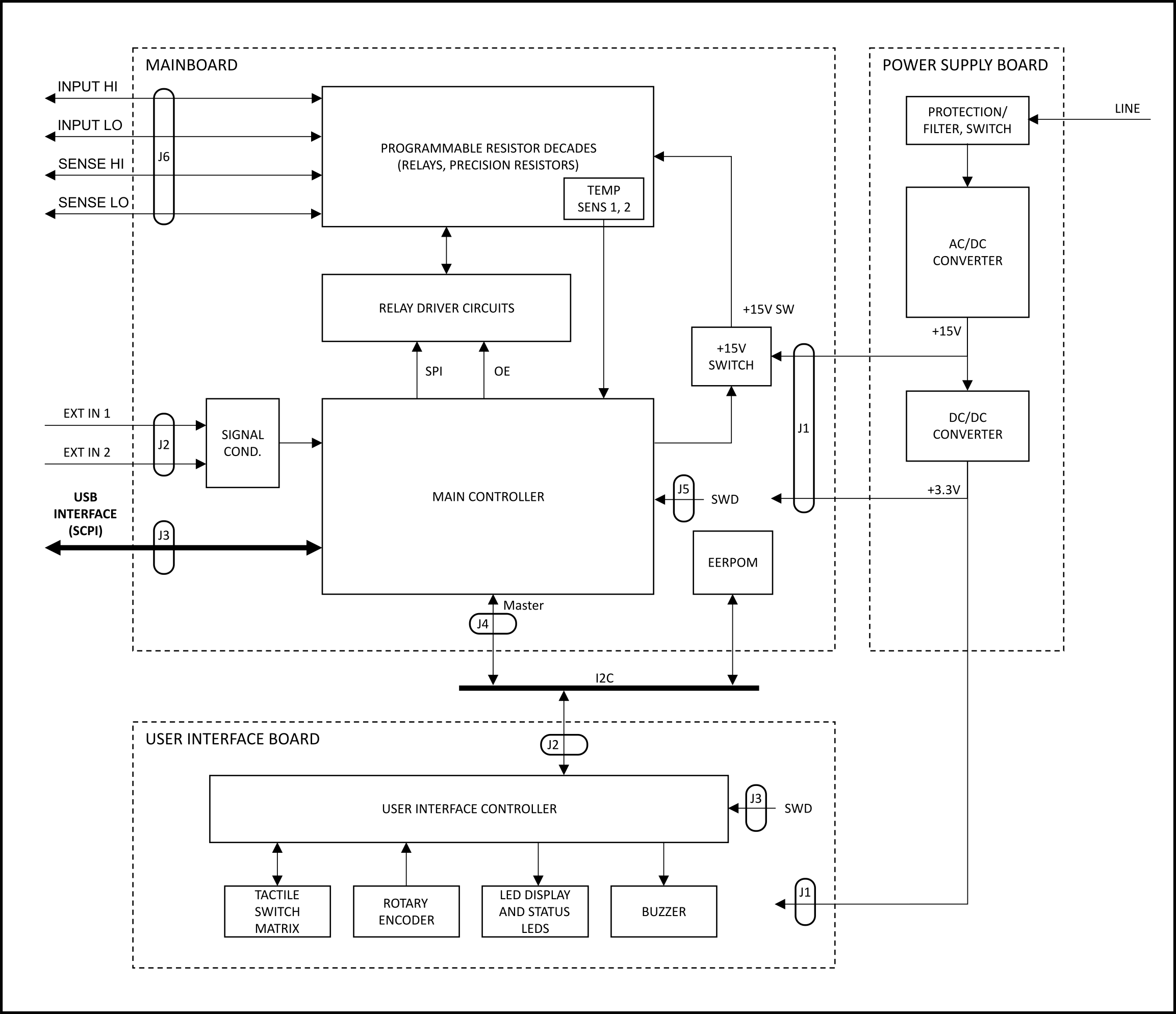
Programmable Decade Resistor: System Design

The block diagram provides an overview of the different circuit groups of each functional block, their internal connections and external interfaces. The Programmable Decade Resistor consists of three main functional blocks: Power supply (Power Supply Board) Programmable decades, control and driver circuits (Mainboard) User Interface (User Interface Board) The power supply board uses an off-the-shelve AC/DC converter to provide a +15V rail. The +15V rail powers the relays on the mainboard as well as a DC/DC converter. A single DC/DC converter generates a +3.3V supply for both the mainboard and the UI board, including the LED display. The power rails are earth-referenced. (Nevertheless, the inputs of the Programmable Decade Resistor are floating thanks to the isolation of the relays.) ...

June 1, 2023 Â· 1 min Â· Sebastian
Screenshot 2023-04-26 195928

Programmable Decade Resistor: Switching (3)

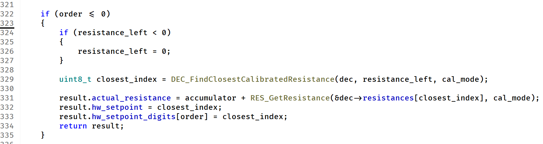
Now that we have a calibrated programmable resistance decade, we can try to make the programmable decade resistor more accuracte - for higher resistance values. Actually, the idea behind that is trivial. I’d like to start with an example in which we set a resistance value of Rset=100.000 kΩR_{set} = 100.000\text{ k}\Omega. (Let’s not worry about temp drift, contact resistance etc.) In my case all resistors have a specified tolerance of 0.1%0.1\%. So we’d expect a resistance somewhere in the range of ...

May 25, 2023 Â· 4 min Â· Sebastian
20230518_102646675_iOS

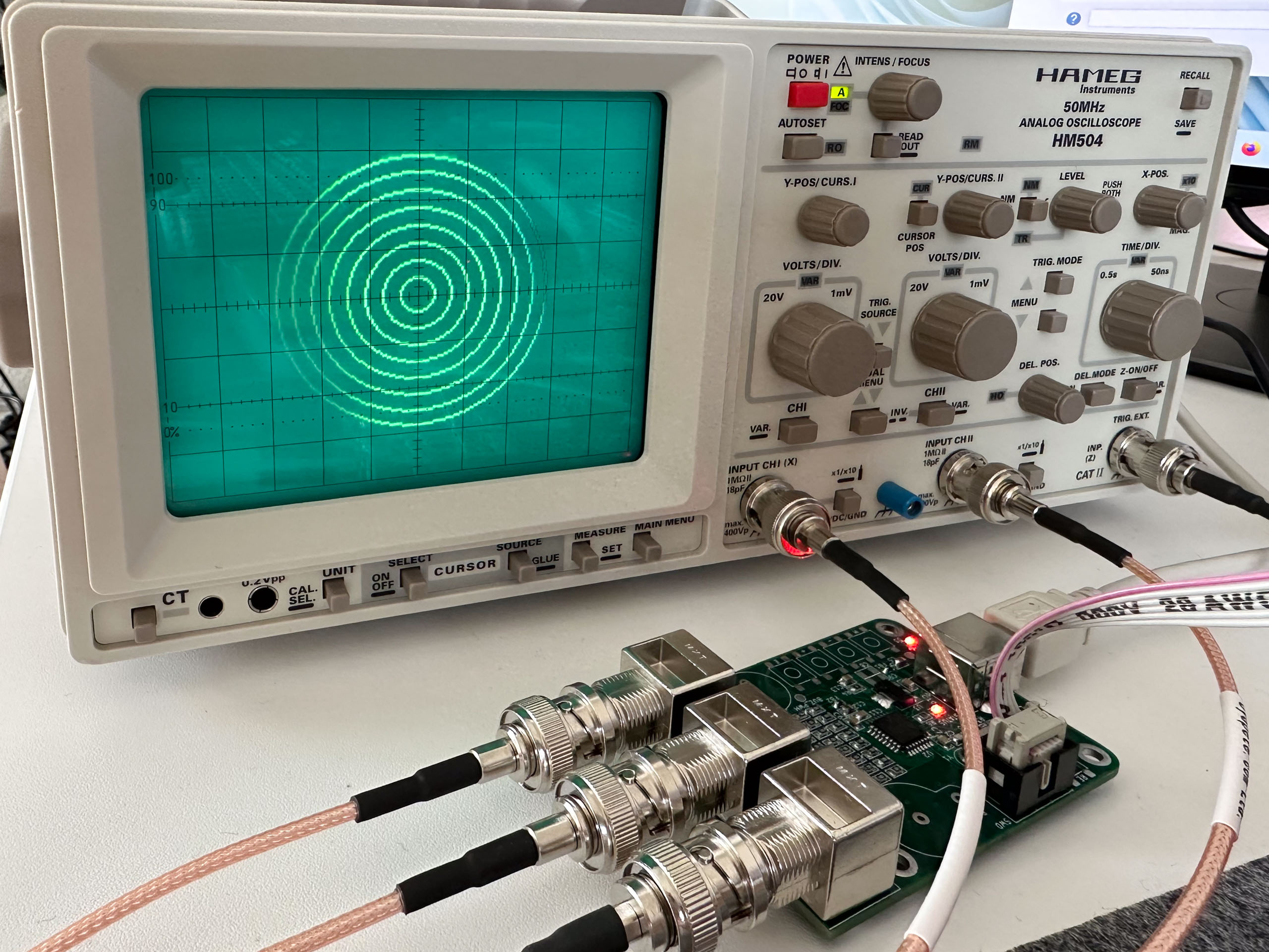
Displaying graphics and text on an oscilloscope screen

While playing with an old Hameg HM504 and the Tektronix 465B oscilloscope that I repaired recently, I thought that I should do yet another mandatory tinker project: Using a microcontroller to write text on an oscilloscope screen via the XYZ-mode. And so I designed a small USB powered board around the STM32G441KBT6 which seems to be my go-to microcontroller nowadays. Its fairly capable dual channel 12-bit DAC (up to 5 MSPS) comes in really handy for generating the x- and y-components. Initially I thought about using a discrete 8-bit R2R network to modulate the brightness with the Z input, but after testing the circuit I finally decided keep it simple and just implement blanking with just a single GPIO output. ...

May 18, 2023 Â· 4 min Â· Sebastian
prog_res_calibration

Programmable Decade Resistor: Switching (2)

In the last post we had a look at the short circuit performance of a decade. This time I want to address the question whether we can make the resistor decade more accurate, despite the fact that the design doesn’t feature any mechanism ( e. g. potentiometer) to adjust resistance values. The short answer: Yes, partially. But first things first. Let’s have a look at another example of a programmable resistor: The Fluke 5450A is a resistance calibrator from the 80’s (or so) that uses fancy precision resistors and relays to provide 17 different resistance values. It misses any adjustment options too - stability is most important for a calibrator. Instead, the calibrator displays a calibrated value of the currently selected resistance that can be programmed by a calibration lab. This is an idea I’d like to adopt. Given the required equipment, performing the calibration of 17 resistance values isn’t that big of a deal, doing it for each of the 1,000,000 resistance values of the programmable decade resistor, however, is a non-starter. ...

May 11, 2023 Â· 3 min Â· Sebastian
20230204_151947578_iOS

Programmable Decade Resistor: Switching (1)

In the previous posts we discussed the topology selection as well as the power handling capabilities of the decade resistor. Now it’s time to have a look at different aspects of switching. Today it’s all about the effect of the contact resistance of the relays, which impacts the performance of the decade resistor, not only, but especially when a decade is shorted. Bypassing upper decades In order to improve the accuracy of the programmable decade resistor at low resistance values, additional switches can be introduced. These switches would bypass all higher decades that otherwise would be in series (shorted), and therefore reduce the error caused by contact resistance. For the intended application it’s probably not justified to add such bypass switches after decades having resistance values ≥10 kΩ\geq 10\text{ k}\Omega, because then ...

April 29, 2023 Â· 3 min Â· Sebastian