Electronics blog
-
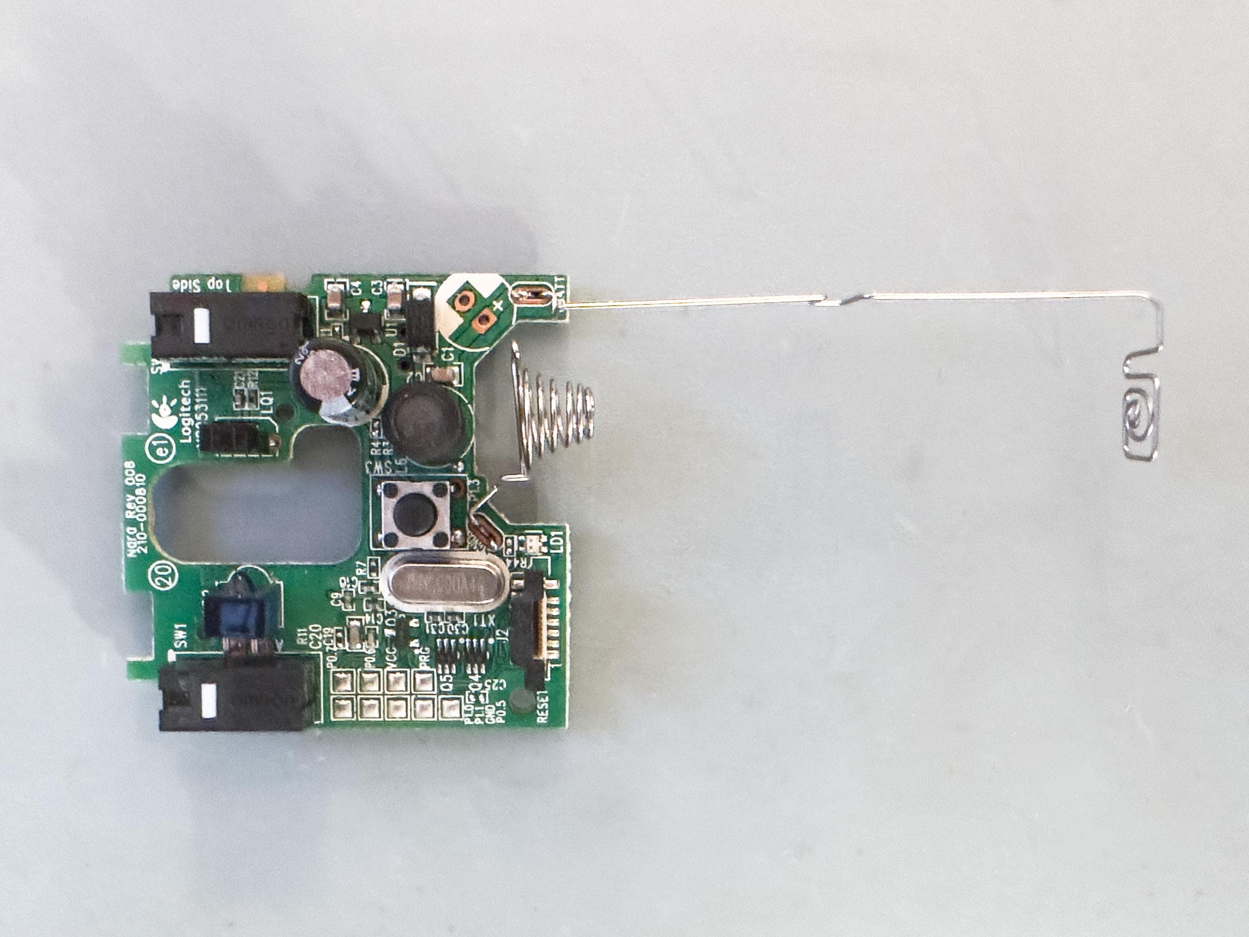
Logitech M310: Mouse Button Repair
For some time it became more and more difficult to get a click out of the mouse wheel switch of my old Logitech M310 mouse – inconvenient in programs like KiCAD. I also have a newer and “better” M705 mouse, however, using this one seemed to increase fatigue compared with the old M310. The mouse…
-
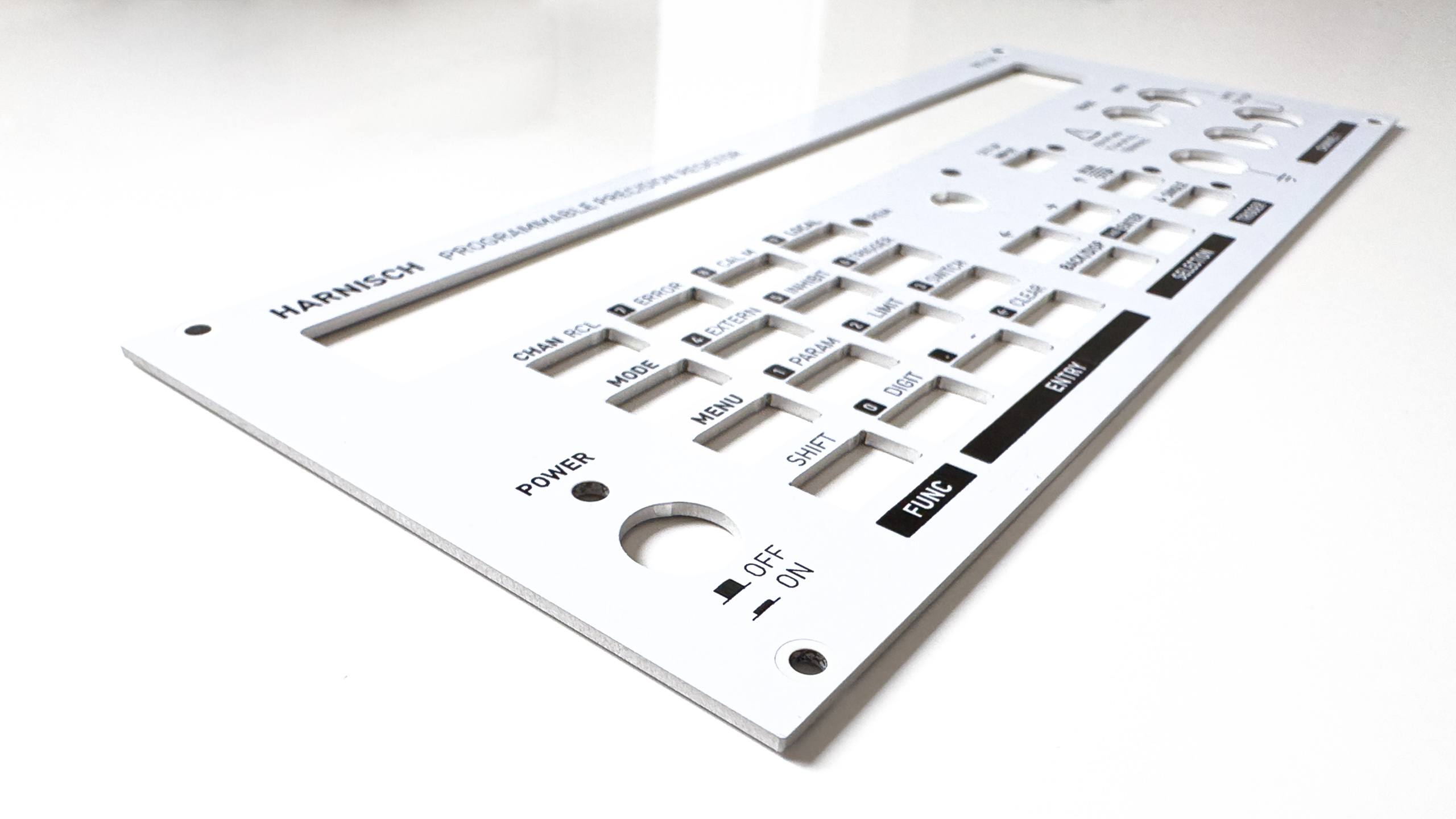
Programmable Decade Resistor: Panels
I was asked a few times how I did the front and rear panels, so this is what I’d like to talk about in this blog. There are different ways to achieve a similar result. For me, the easiest and most cost-effective solution was to just design another PCB – I know how KiCAD works…
-
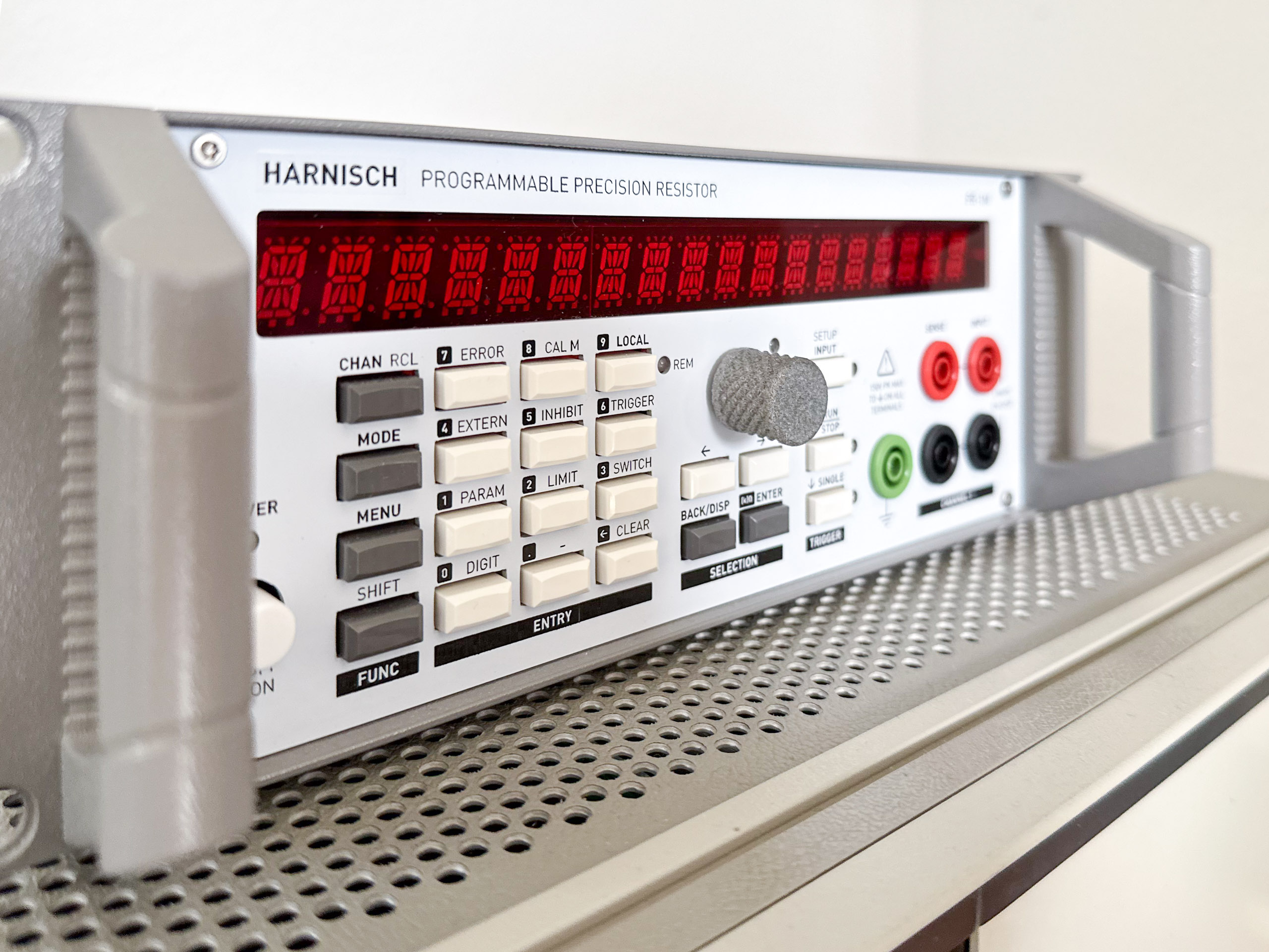
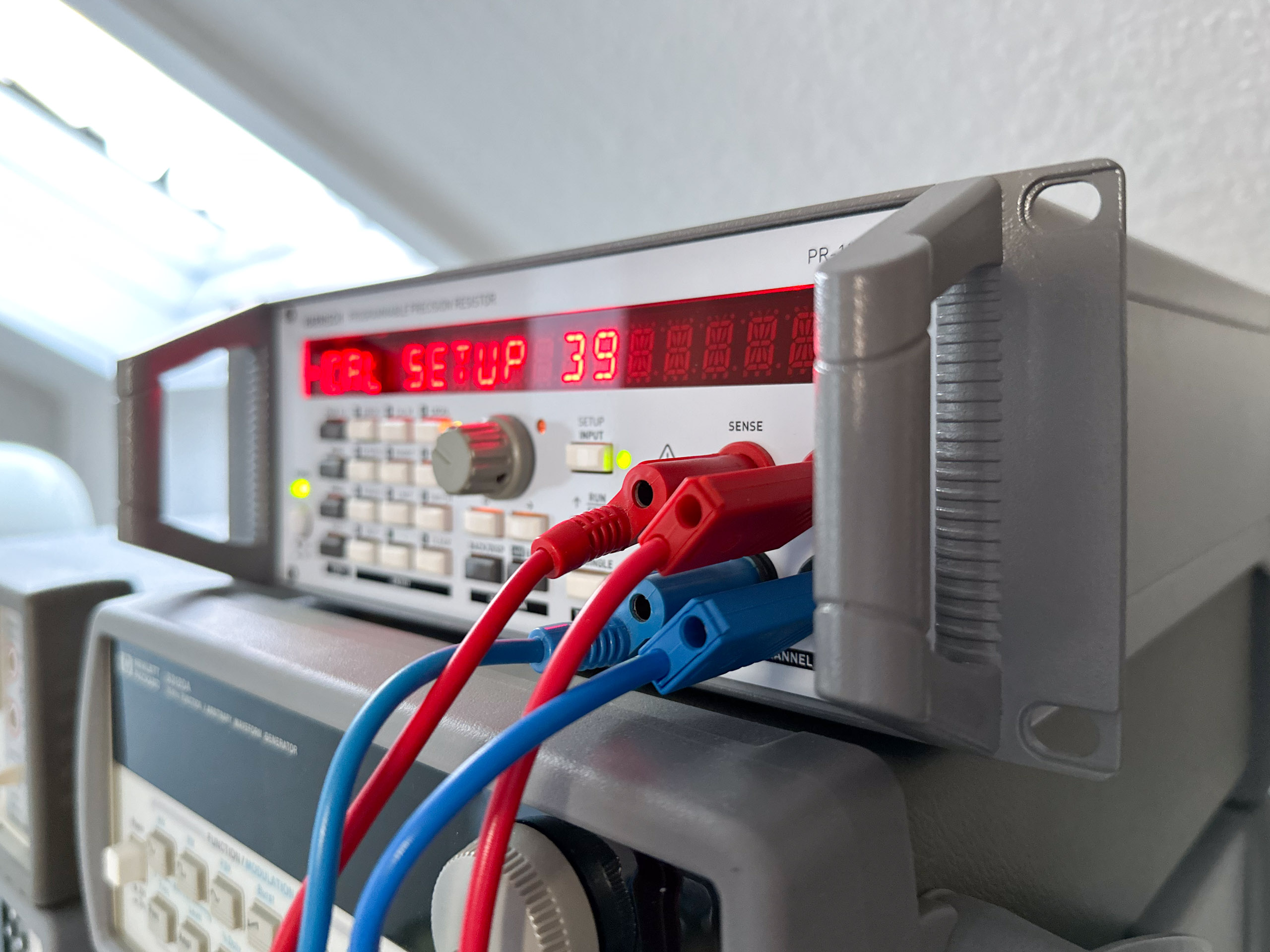
Programmable Decade Resistor: Components
After being asked about some aspects of the mechanical design and components used a few times, I’d like to address those questions. I have to admit that I’m neither very good at the mechanical design, nor do I have a 3d printer (yet) or a shop where I can do metal work myself. That being…
-
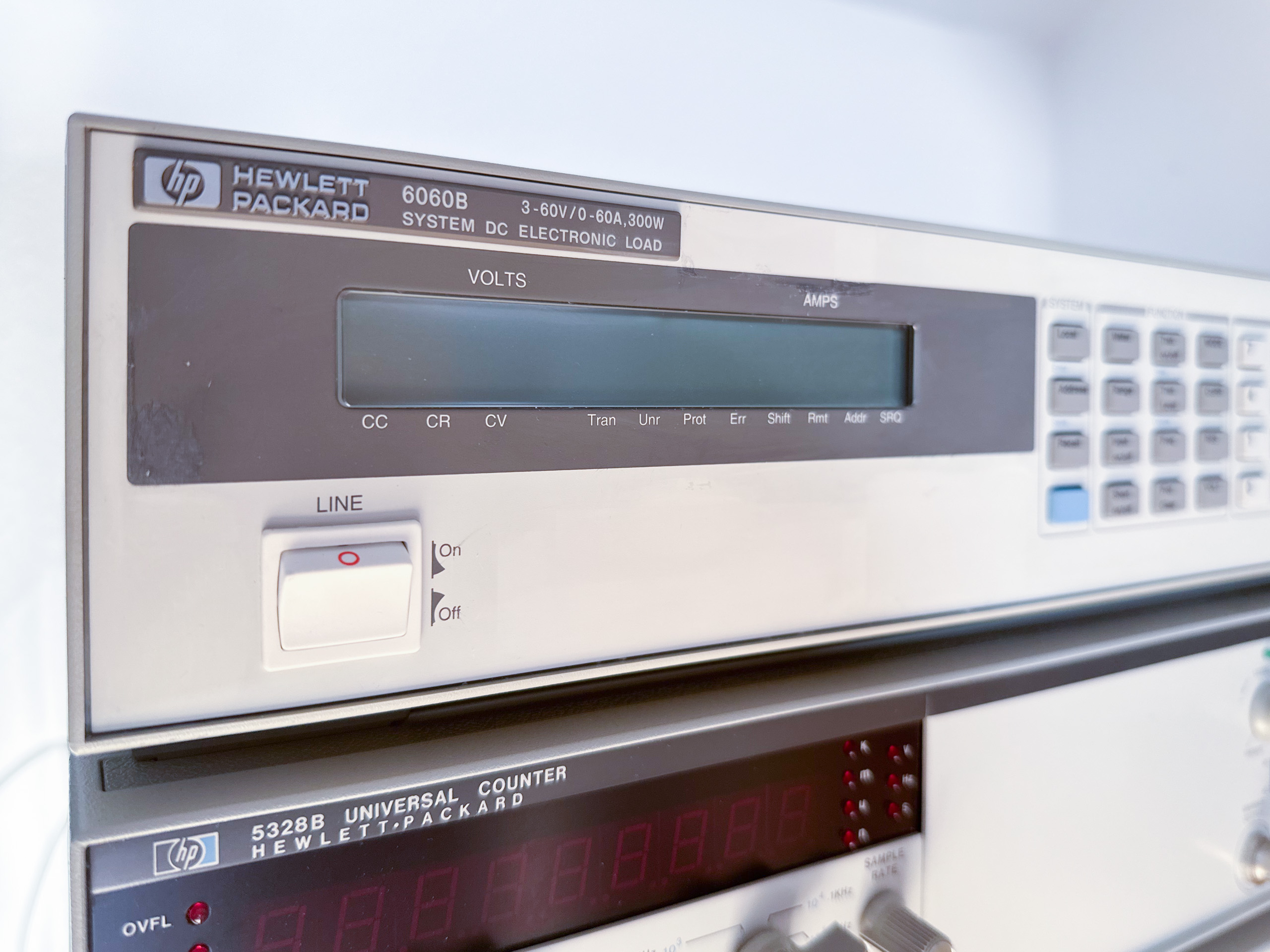
HP 6060B System DC Electronic Load: Adjustment
Currently, the unit’s setpoint accuracy isn’t all that great (readback resolution is limited as well, but shows the offset): Regardless of the range it has an offset of about +20 mA. Sure, for a unit capable of 60 A that seems reasonable, and well within its specs of ±0.1% ±75 mA. But since I’ll use…
-
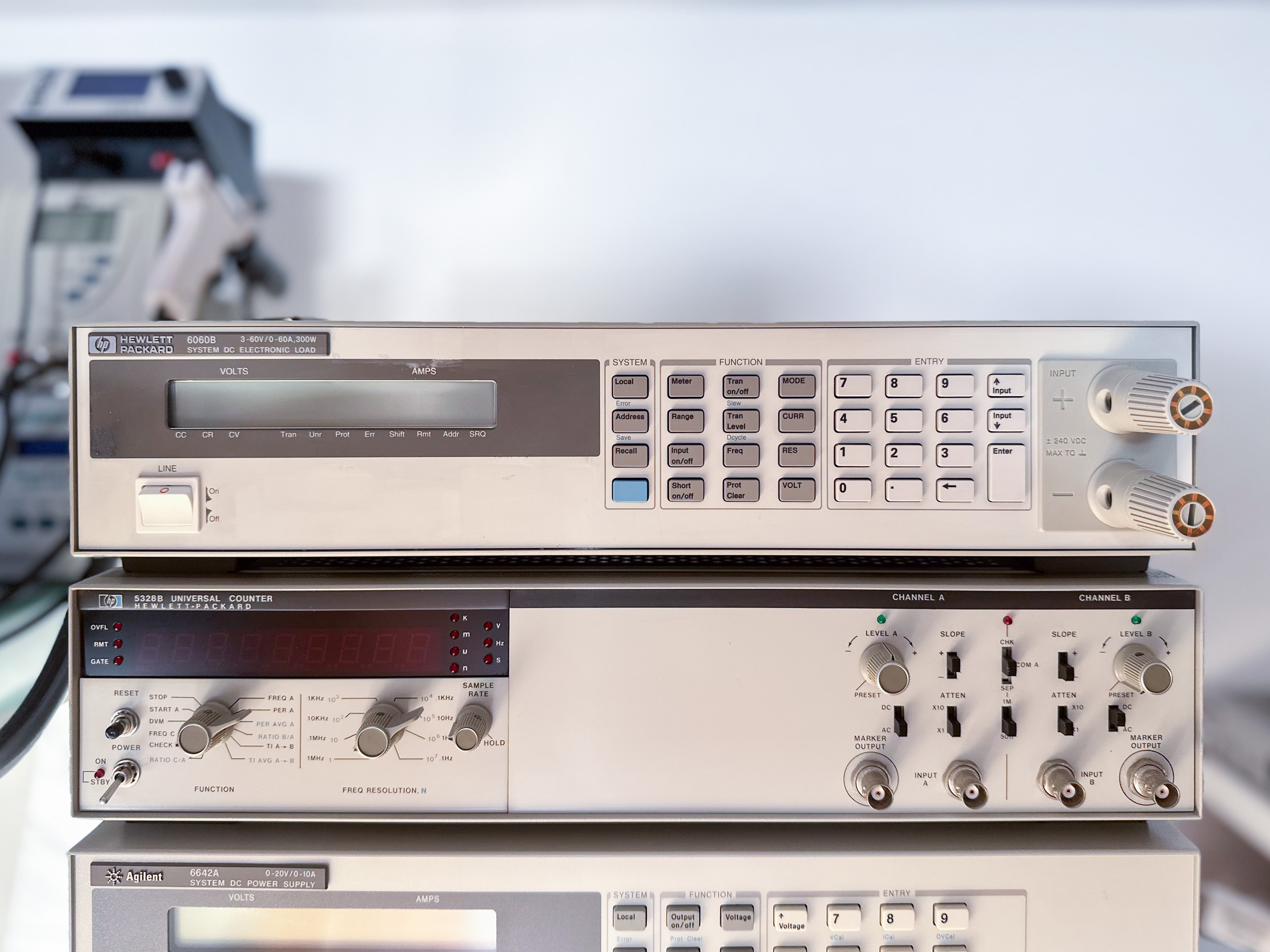
HP 6060B System DC Electronic Load: Teardown, Service
I recently got my hands on a HP 6060B System DC Electronic Load (later also sold as Agilent 6060B). My unit has option 020 installed: Comically large binding posts also on the front panel. This option certainly is not unheard of, but not too common either. Retrofitting is possible, but can be quite some work.…
-
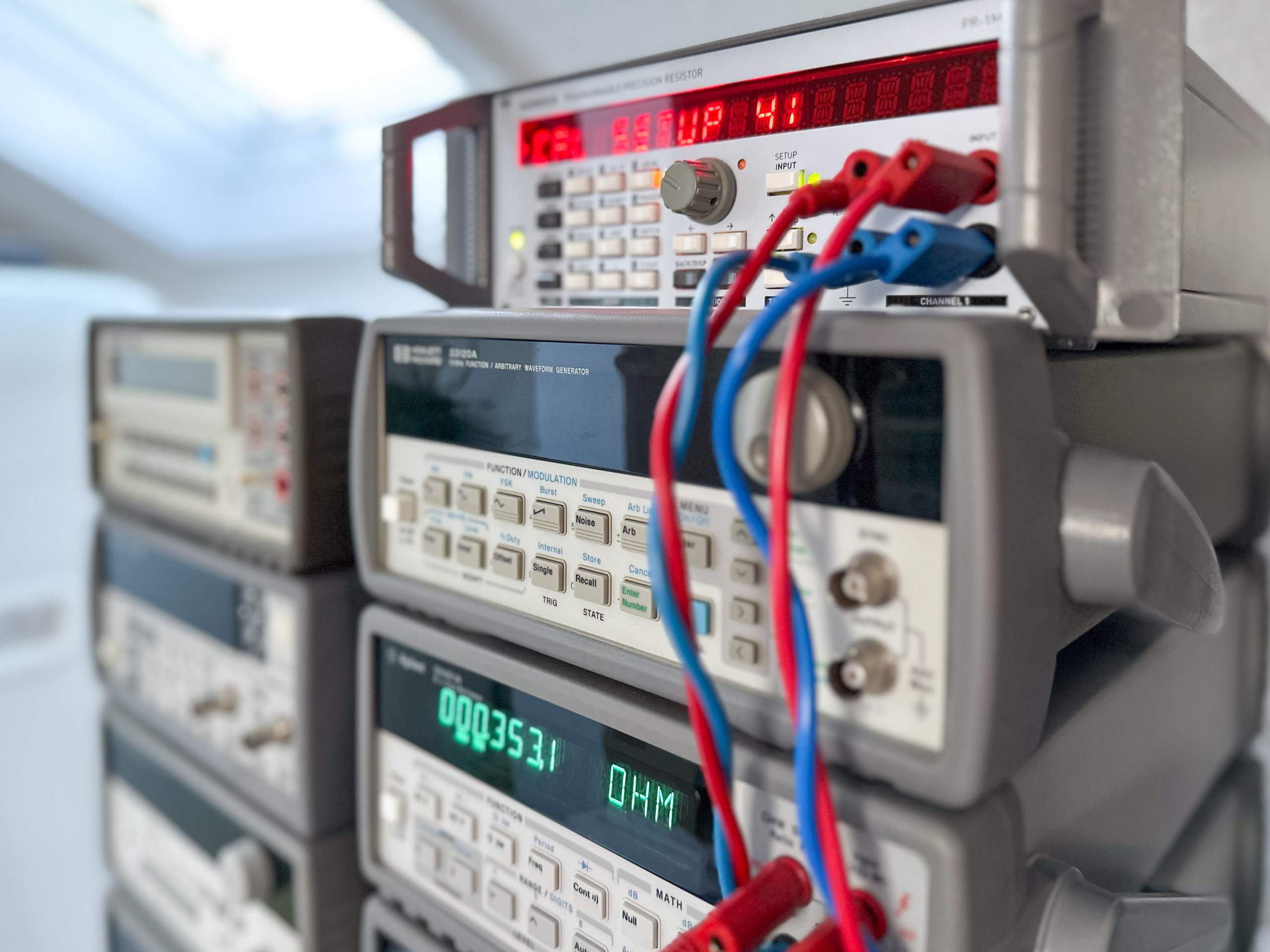
Programmable Decade Resistor: Improved results
After the modification described in the previous post I let the the “adjustment”/calibration procedure run again. Five days later I repeated the calibration (not the adjustment). As before, all measurements are performed with an Agilent 34401A 6.5 digit multimeter. Accuracy of the resistance First up is a diagram that shows the absolute value of the…
-

About word clocks…
A bit over a decade ago I built a word clock – one of my first microcontroller projects. The project was fairly expensive: It uses a large stainless steel front panel (ca. 39cm x 39cm, laser cut) and a similar sized PCB. Over the years I had to resolder one or two of the RGB…
-
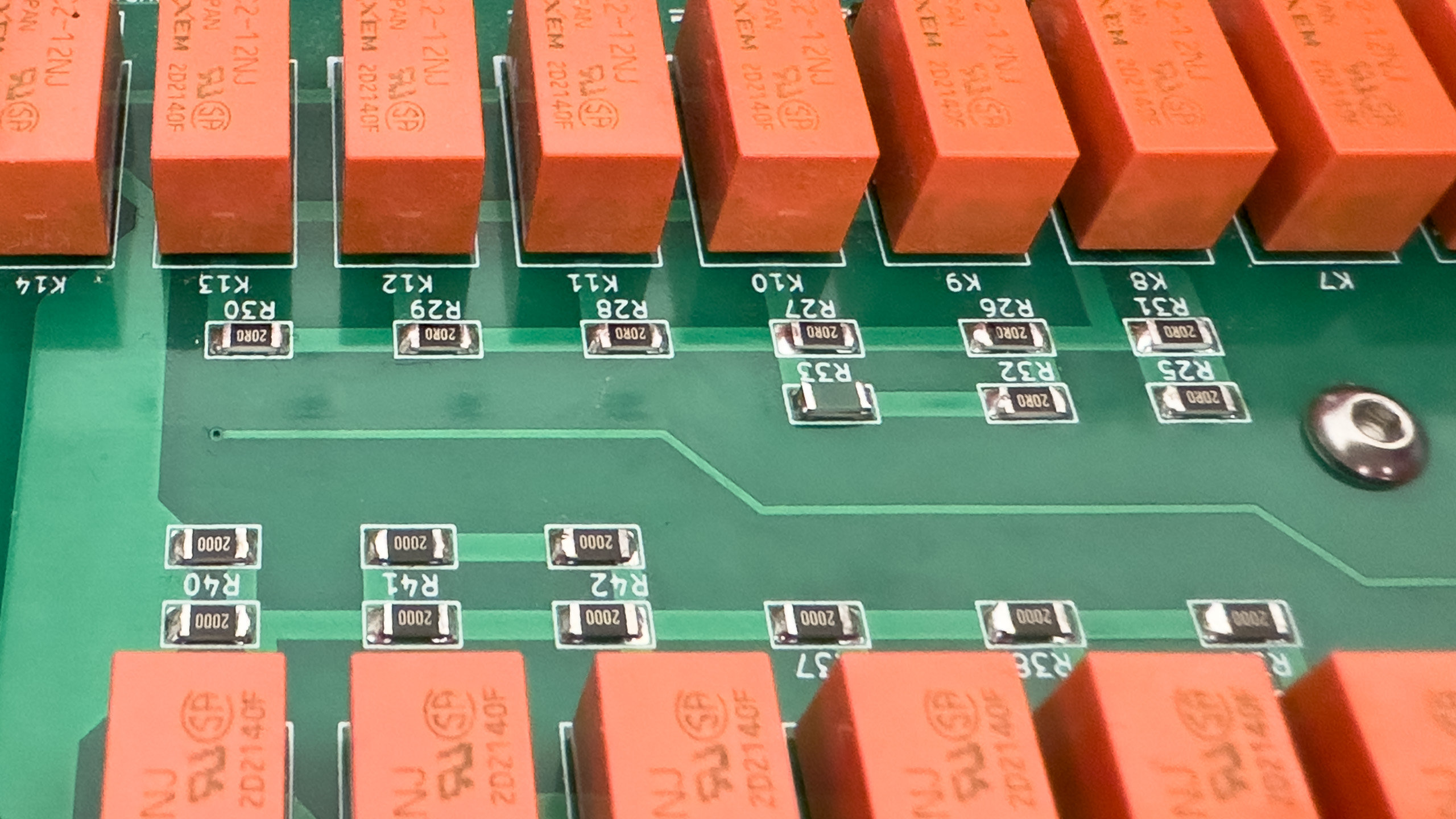
Programmable Decade Resistor: Optimization
I went into this project with the thought that it will be a rather small one. This certainly influenced some decisions I made along the way. Now that the project had evolved into a much larger thing than initially anticipated it’s reasonable to have another look at possible optimizations, albiet the calibration results were already…
-
Progammable Decade Resistor: Calibration results
In one of the previous posts I covered in depth, how I use the term “calibration” in the context of the programmable decade resistor and how the calibration procedure works. Today it’s all about the result. Also, I’d like to mention the first post in which I defined a rather loose accuracy goal of \(\ll\pm…